retractor

a retractor and retraction technology, applied in the field of retractors, can solve problems such as damage to the incision area, and achieve the effect of small number of operations and stable retraction sta

Inactive Publication Date: 2014-01-30
MORITA MFG CO LTD
View PDF4 Cites 5 Cited by
  • Summary
  • Abstract
  • Description
  • Claims
  • Application Information

AI Technical Summary

Benefits of technology

[0029]Owing to the present invention, a retractor for realizing a ...

Problems solved by technology

If the fastened state of the handle is loosened, the U-shaped spring-like ra...

Method used


Image

  • retractor
  • retractor
  • retractor

Examples


Embodiment Construction

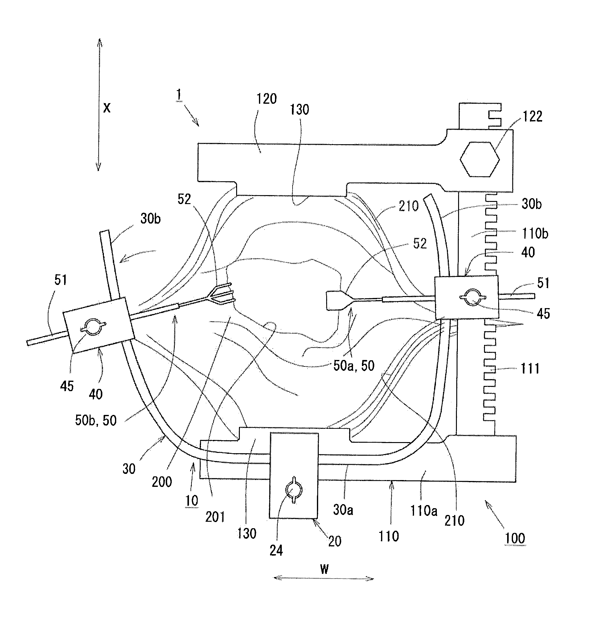
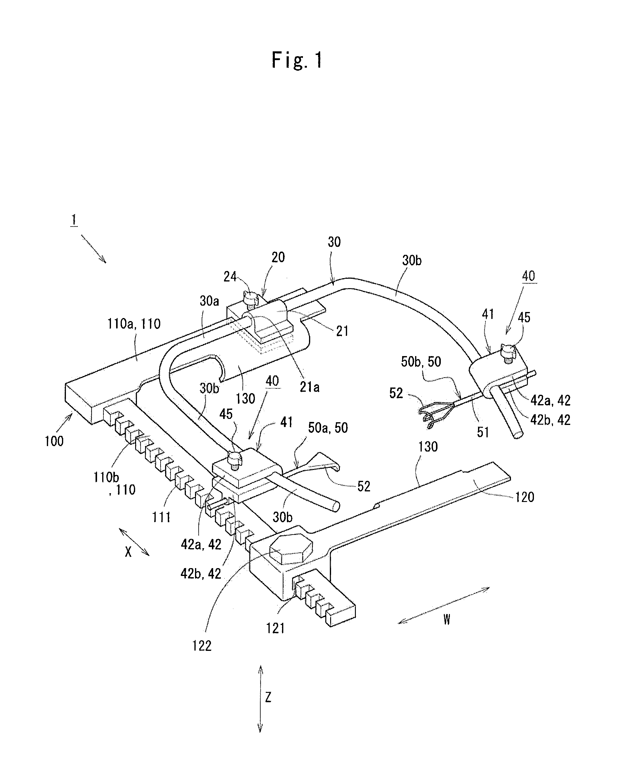
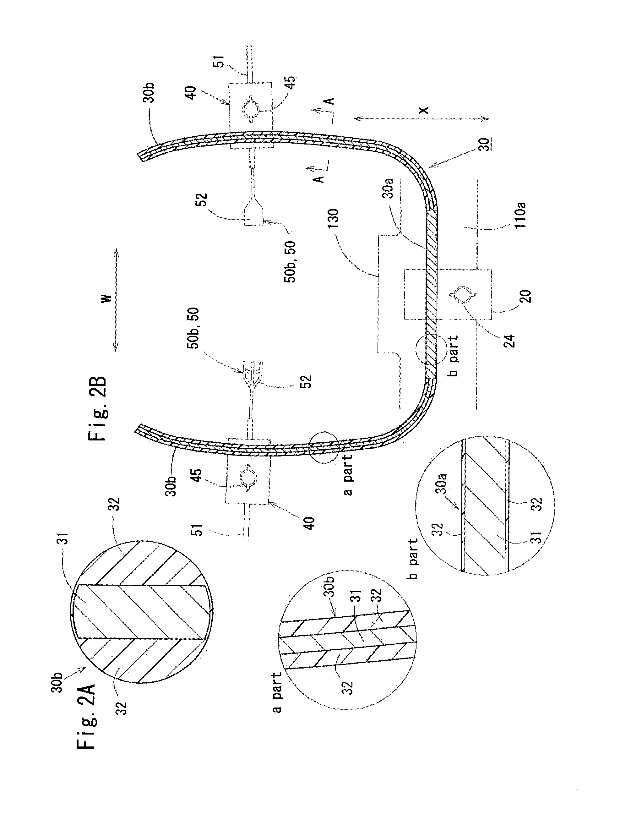
[0040]An embodiment of the present invention will be described with reference to the drawings. FIG. 1 is an isometric view of a retractor unit 1, and FIGS. 2A and 2B illustrate a support arm 30. In more detail, FIG. 2A is a cross-sectional view of an extended aim portion 30b shown in FIG. 2B taken along line A-A in FIG. 2B, and FIG. 2B is a cross-sectional view of the support arm 30 taken in a planar direction. The circled figures in FIG. 2B labeled “a” and “b” are respectively enlarged views of the “a” part and the “b” part in FIG. 2B.

[0041]FIG. 3 is an isometric view illustrating a virtual plane F, FIG. 4 is a cross-sectional view of a fixing table 20, and FIG. 5 is a cross-sectional view of a hook support section 40. FIG. 6 is a side view illustrating attachment and fixation of the hook support section 40, FIG. 7 is a side view illustrating adjustment of the attaching position of the retractor hook 50 to the hook support section 40, and FIG. 8 is a side view illustrating adjustme...


PUM


Abstract

A retractor includes a central fixed portion, an extended arm portion extending on both sides of the central fixed portion, and a hook support section which is attached to the extended arm portion so as to be slidable in a longitudinal direction and supports a retractor hook is formed of a plastically deformable composite member for, when receiving a deformation load of causing a bending deformation, permitting the extended arm portion to be plastically deformed in an in-plane direction Fh in a virtual plane F, which is formed of the central fixed portion and the extended arm portion, while restricting the extended arm portion regarding the deformation in an out-of-plane direction Fv.

Description

TECHNICAL FIELD[0001]The present invention relates to a retractor used for, for example, heart surgery and the like, and in more detail, to a retractor having an accessory such as a retractor hook or the like mounted thereon.BACKGROUND ART[0002]For example, in surgery of incising a body site such as heart surgery or the like, various retractors are used for enlarging the visual field of surgical procedure in the incised area. For example, a retractor as described in Patent Document 1 has been proposed.[0003]For example, the retractor described in Patent Document 1 is used with a rib spreader, and has the following structure. On top of the rib spreader adjustable to be wider or narrower to suit to the size of the area of surgical procedure, a flexible U-shaped spring-like rail having a circular cross-section is provided, and retractor hook support means is movably supported by the spring-like rail. It is described that owing to such a structure, a desired retracted state is realized....

Claims


Application Information

Patent Timeline
IPC IPC(8): A61B17/02
CPCA61B17/0206
Inventor NAKAO, MASAKAZU
Owner MORITA MFG CO LTD
Why Eureka
Try Eureka