Displaying Computer-Aided Detection Information With Associated Breast Tomosynthesis Image Information

a technology of image information and breast tomosynthesis, applied in the field of display of cad results, can solve the problems of inability to provide “true” x-ray tomosynthesis imaging, high anisotropic, and often artifact-laden images, and achieve the effect of increasing the certainty of finding

Active Publication Date: 2014-01-30
HOLOGIC INC
View PDF2 Cites 47 Cited by
  • Summary
  • Abstract
  • Description
  • Claims
  • Application Information

AI Technical Summary

Benefits of technology

[0012]According to another preferred embodiment, an interactive user interface for displaying breast x-ray tomosynthesis information and related CAD information is provided, in which there is received the above-described image slices and CAD findings. Displayed on a user display is a two dimensional diagnostic image comprising either (i) a single one of the received image slices, or (ii) a plurality of depthwise adjacent ones of said received image slices slabbed together, the diagnostic image thus being characterized by an image depth and an image thickness. Provided on the user display in visual proximity to the two dimensional diagnostic image is a graphical depth navigation tool configured to graphically communicate to a user the image depth and the image thickness of the currently displayed diagnostic image, and to allow user control thereof. The graphical depth navigation tool comprises (a) a slice ruler spatially extending in a first direction representative of said image depth, and (b) a slice slider icon disposed along the slice ruler at a user-controllable position corresponding to the image depth. Further displayed on the user display is a plurality of CAD indicator icons corresponding respectively to the plurality of CAD findings, each CAD indicator icon running near and along the slice ruler and spanning a contiguous segment thereof that corresponds in depthwise position and extent to the subset of image slices spanned by the associated CAD finding. Further displayed is at least one single-slice highlighting mark on each of the CAD indicator icons, each single-slice highlighting mark being positioned on its associated CAD indicator icon at a location indicative of the slice depth of a respective one of the subset of image slices spanned by the associated CAD finding and containing viewable image information corresponding to that associated CAD finding.
[0013]According to another preferred embodiment, an interactive user interface for displaying breast x-ray tomosynthesis information and related CAD information is provided, in which there is received the above-described image slices and CAD findings, and in which there is displayed the above-described two-dimensional diagnostic image associated with the breast volume. Each of the image slices corresponds to a slice in the breast volume that is generally transverse to a direction of compression. Further displayed on the user display in visual proximity to the two dimensional diagnostic image is a graphical navigation tool configured to graphically communicate to a user the image depth and image thickness of the currently displayed diagnostic image, and to allow user control thereof. The graphical navigation tool comprises a two-dimensional outline image in miniaturized form of the breast volume as projected onto a plane along the direction of compression, the two-dimensional outline image having a depth dimension corresponding to the direction of compression and a lateral dimension normal to said depth dimension. The graphical navigation tool further comprises a slice slider bar extending across at least a portion of the outline image in a direction parallel to the lateral dimension, the slice slider bar having a user-controllable position in the depth dimension that corresponds to the image depth of the currently displayed diagnostic image. Further displayed on the user display is a plurality of CAD indicator icons corresponding respectively to the plurality of CAD findings, each CAD indicator icon being positioned on the outline image at a location representative of the location of the associated CAD finding in the breast volume. Each CAD indicator icon has a position and extent in the depth dimension that corresponds to the slice depths of the image slices spanned by the associated CAD finding.
[0014]Provided according to another preferred embodiment is a method for processing and displaying information related to a plurality of breast x-ray tomosynthesis cases, each case comprising at least one breast x-ray tomosynthesis data volume associated with at least one breast of a patient. For each case, a target count “N” representing a target number of marked CAD findings to be displayed to a user on a review workstation in conjunction with the at least one data volume is determined. Importantly, the target count N is independent of any breast tissue image information contained in any of the data volumes for any of the cases. For each case, a set of candidate CAD findings is received, each candidate CAD finding being associated with a potentially suspicious lesion in the at least one breast as identified by a CAD algorithm and characterizing the potentially suspicious lesion by a plurality of computed features including a certainty of finding metric. For each case, up to the target count N of the candidate CAD findings are designated as being marked CAD findings according to the steps of (a) designating all of the candidate CAD findings as marked CAD findings

Problems solved by technology

Although x-ray tomosynthesis imaging and computed tomography (CT) imaging are both generally considered to be three dimensional imaging modalities, there are differences between these two modalities that can have an impact on the way their associated data volumes are best processed and/or reviewed for the detection of anatomical abnormalities.
However, unlike with CT imaging, x-ray tomosynthesis imaging is not capable of providing a “true” value for the x-ray absorption property of any particular point in the imaged volume, but instead only provides such value in inseparable combination with varyingly “blurred” versions of the absorption property from other parts of the imaged volume.
The number of distinct reconstructed image slices containing useful and anatomically differentiating information is substantial

Method used


Image

  • Displaying Computer-Aided Detection Information With Associated Breast Tomosynthesis Image Information
  • Displaying Computer-Aided Detection Information With Associated Breast Tomosynthesis Image Information
  • Displaying Computer-Aided Detection Information With Associated Breast Tomosynthesis Image Information

Examples


Embodiment Construction

[0034]In describing preferred embodiments illustrated in the drawings, specific terminology is employed for the sake of clarity. However, the disclosure of this patent specification is not intended to be limited to the specific terminology so selected and it is to be understood that each specific element includes all technical equivalents that operate in a similar manner.

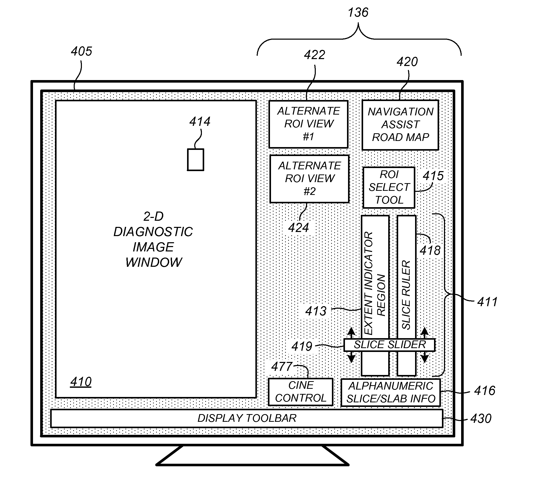
[0035]Although the following description refers to user interfaces of one or more preferred embodiments to facilitate dynamic review of breast x-ray tomosynthesis data (either during a first or second reading of the image data) it will readily be appreciated by one of skill in the art that one or more concepts of the preferred embodiments may be extended for use in viewing CAD information available in any dimension of a three-dimensional data set provided by any means, and ‘displayed’ in any manner. Thus the below description should be viewed only as illustrative and not limiting. Although certain terms and definiti...


PUM


Abstract

Methods, systems, and related computer program products for processing and displaying computer-aided detection (CAD) information associated with medical breast x-ray images, such as breast x-ray tomosynthesis volumes, are described. An interactive graphical user interface for displaying a tomosynthesis data volume is described that includes a display of a two-dimensional composited image having slabbed sub-images spatially localized to marked CAD findings. Also described is a graphical navigation tool for optimized CAD-assisted viewing of the data volume, comprising a plurality of CAD indicator icons running near and along a slice ruler, each CAD indicator icon spanning a contiguous segment of the slice ruler and corresponding in depthwise position and extent to a subset of image slices spanned by the associated CAD finding, each CAD indicator icon including at least one single-slice highlighting mark indicating a respective image slice containing viewable image information corresponding to the associated CAD finding.

Description

CROSS-REFERENCE TO RELATED APPLICATIONS[0001]This application is a continuation of U.S. patent application Ser. No. 12 / 899,253, filed Oct. 6, 2010, now U.S. Pat. No. 8,547,402, which claims the benefit of U.S. Provisional Patent Application Ser. No. 61 / 249,311, filed Oct. 7, 2009, entitled “Device and Method for Displaying CAD Marks in Three Dimensional Images,” which is incorporated by reference herein. The subject matter of one or more preferred embodiments described herein relates to the subject matter of the commonly assigned U.S. Ser. No. 12 / 330,176, filed Dec. 8, 2008, entitled “Device and Method for Displaying Feature Marks Related to Features in Three Dimensional Images on Review Stations,” which published on Jun. 10, 2010 as US 2010 / 0141654A1 and which is incorporated by reference herein.FIELD[0002]This patent specification relates to the computer-aided detection (CAD) of anatomical abnormalities in medical images. More particularly, this patent specification relates to the...

Claims


Application Information

Patent Timeline
IPC IPC(8): G06F3/0484A61B6/00
CPCA61B6/5217G06F3/04847A61B6/025A61B6/0414A61B6/466A61B6/467A61B6/502A61B6/5294G06F3/04845G06T11/008G06T19/00G06T2200/24G06T2210/41G06T2211/436G06T2219/004G16H30/20G16H30/40G16H40/63G16H50/20G16H50/50A61B6/463A61B6/465G06F3/04815G06F3/04817G06T11/003G06T11/60G06T15/08G06T2207/20104G06T2207/30068G06T2207/30204
Inventor KREEGER, KEVIN A.MARSHALL, JULIANHITZKE, GEORGIA K.CHUI, HAILI
Owner HOLOGIC INC
Why Eureka
Try Eureka