Rail systems and methods for installation and operation of photovoltaic arrays

a photovoltaic array and rail system technology, applied in the field of rail systems and methods for installing and operating photovoltaic arrays, can solve the problems of difficult installation of photovoltaic arrays, uneven terrain, etc., and achieve the effects of reducing the time and cost of installation and operation, reducing maintenance and operation costs of photovoltaic arrays, and significantly improving the service of photovoltaic arrays

Inactive Publication Date: 2014-02-06
ALION
View PDF6 Cites 16 Cited by
  • Summary
  • Abstract
  • Description
  • Claims
  • Application Information

AI Technical Summary

Benefits of technology

[0017]The present invention provides advantages over conventional technology. Certain embodiments of the present invention provide a photovoltaic array based on at least one or more modular rails that enable partial or full automation of many installation and operational tasks. Some embodiments of the present invention can reduce time and cost of installation and operation of a photovoltaic array. For example, the maintenance and operation cost of the photovoltaic array is significantly reduced. In another example, the servicing of the photovoltaic array (e.g., diagnostics, cleaning, and / or snow removal) is significantly improved. Certain embodiments of the present invention provide one or more vehicles that can move along one or more modular rails and / or one or more index rails to navigate throughout the photovoltaic array and perform various tasks. Some embodiments of the present invention provide a photovoltaic array that does not need panel-to-panel cable strain relief. Certain embodiments of the present invention provide an installation method and system that eliminates expensive junction boxes and standardized cable interconnects of conventional PV modules. Some embodiments of the present invention can improve wind tolerance of a photovoltaic array.

Problems solved by technology

The installation of photovoltaic arrays often presents logistical challenges.
Not only does the site for the photovoltaic array need to be properly prepared, but large quantities of materials also need to be transported to and within the site.
For example, the site for the photovoltaic array may have existing vegetation that would interfere with the installation and operation of the photovoltaic array.
The site may also have uneven terrain that usually requires extensive grading and earth moving.
Each of these operations can be time-consuming and expensive.
Depending upon the terrain, soils, and weather, simply getting equipment and materials from one end of the array to another often poses significant challenges, especially if the ground is muddy.
As with the installation, these operational needs can also be time-consuming and expensive.

Method used


Image

  • Rail systems and methods for installation and operation of photovoltaic arrays
  • Rail systems and methods for installation and operation of photovoltaic arrays
  • Rail systems and methods for installation and operation of photovoltaic arrays

Examples


Embodiment Construction

[0036]The present invention is directed to utility arrays. More particularly, the invention provides systems and methods for installation and operation of photovoltaic arrays. Merely by way of example, the invention has been applied to solar farms. But it would be recognized that the invention has a much broader range of applicability.

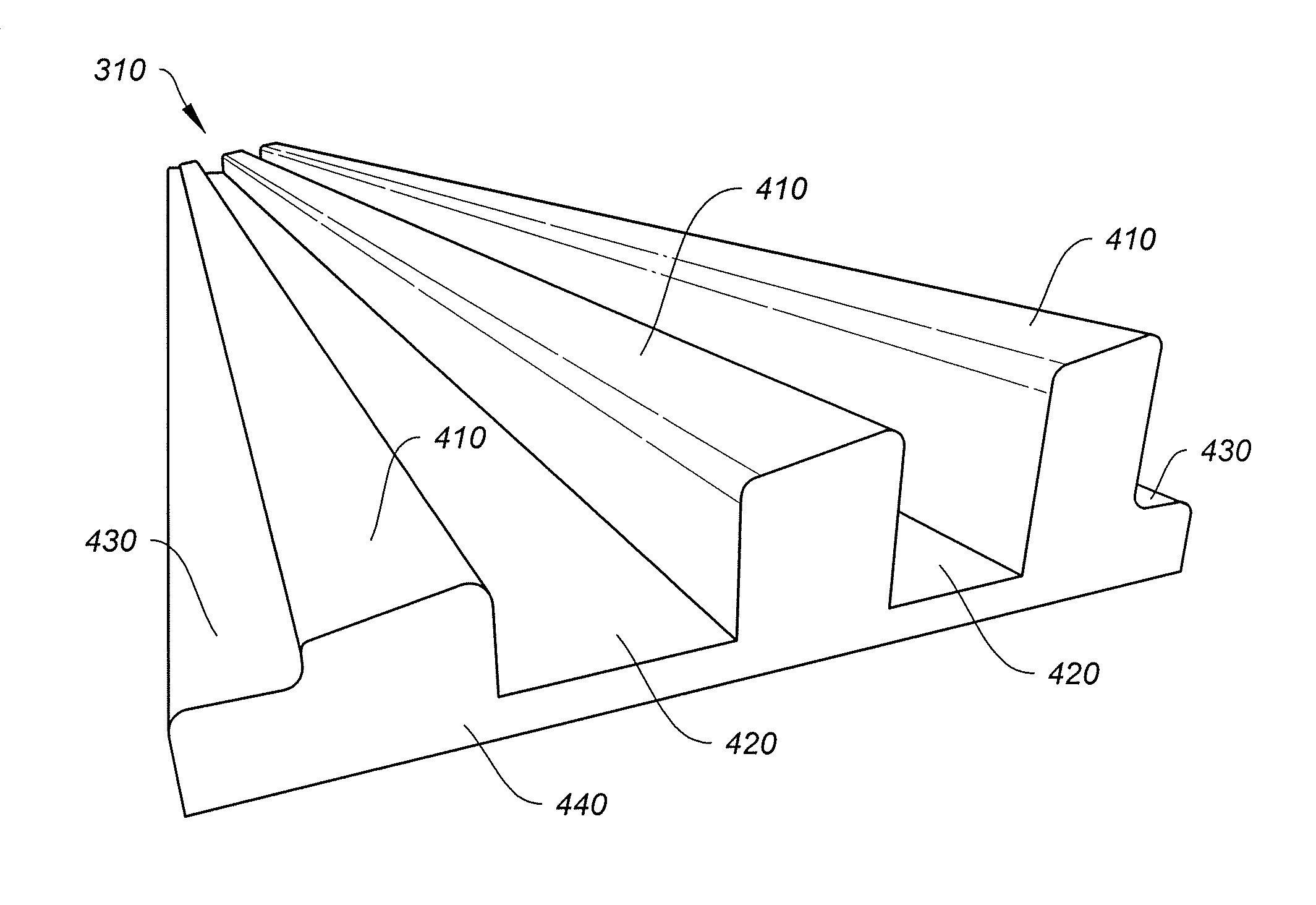
[0037]FIG. 3 is a simplified diagram showing a system for installation and operation of a photovoltaic array according to one embodiment of the present invention. This diagram is merely an example, which should not unduly limit the scope of the claims. One of ordinary skill in the art would recognize many variations, alternatives, and modifications. In FIG. 3, the photovoltaic array 300 is organized around one or more modular rails 310 (e.g. photovoltaic (PV) rails) oriented in a first direction. For example, the photovoltaic array 300 includes one or more photovoltaic modules. In another example, these modular rails 310 are arranged in a general east-...


PUM

PropertyMeasurementUnit
lengthaaaaaaaaaa
adhesiveaaaaaaaaaa
poweraaaaaaaaaa

Abstract

Rail system and method for a photovoltaic array. The system includes at least one modular rail in a first direction. The modular rail includes a first vehicle support surface along the first direction and a first mounting surface along the first direction. The first vehicle support surface is configured to support at least a first vehicle moving in the first direction, and the first mounting surface is configured to support one or more photovoltaic modules mounted on the first mounting surface.

Description

1. CROSS-REFERENCES TO RELATED APPLICATIONS[0001]This application claims priority to U.S. Provisional No. 61 / 328,575, filed Apr. 27, 2010, commonly assigned and incorporated by reference herein for all purposes.[0002]Additionally, this application is related to U.S. patent application Ser. No. 13 / 043,286, commonly assigned, incorporated by reference herein for all purposes.2. BACKGROUND OF THE INVENTION[0003]The present invention is directed to utility arrays. More particularly, the invention provides systems and methods for installation and operation of photovoltaic arrays. Merely by way of example, the invention has been applied to solar farms. But it would be recognized that the invention has a much broader range of applicability.[0004]Photovoltaics convert sunlight into electricity, providing a desirable source of clean energy. FIG. 1 is a simplified diagram of a conventional photovoltaic array. The photovoltaic array 100 includes strings 1, 2, 3, 4, . . . n, where n is a positi...

Claims


Application Information

Patent Timeline
Patent Type & Authority Applications(United States)
IPC IPC(8): H05K13/00B21C23/00
CPCB21C23/00H05K13/00Y02E10/50B25J5/007Y02E10/47H02S20/00H02S20/10H02S40/36H02S40/34Y10T29/49002F24S25/11F24S25/16F24S2080/012F24S2025/014H02S40/10H02S40/32B08B1/008H02S50/00H05K13/0015
Inventor SWAHN, ANDERSOELS, WOLFGANG
Owner ALION
Why Eureka
Try Eureka