Light-emitting device

Inactive Publication Date: 2014-02-06
EPISTAR CORP
View PDF6 Cites 13 Cited by
  • Summary
  • Abstract
  • Description
  • Claims
  • Application Information

AI Technical Summary

Benefits of technology

[0009]The application relates to a light-emitting diode device, and more particularly, to a light-emitting diode device emitting light uniformly and having a high reliability. Wherein the light-emitting diode device comprises the structure with a plurality of light-emitting diode units formed on a single substrate.
[0010]A light-emitting diode device is disclosed, which includes a substrate; a plurality of light-emitting diode units, each of the light-emitting diode units being an equilateral polygon with more than four sides, are disposed on the substrate; wherein each of the light-emitting diode units includes a first electrical connecting area disposed along a first side of the light-emitting diode unit, a second electrical connecting area disposed along a second side of the light-emitting diode unit, and a conductive connecting structure disposed on each of the electrical connecting areas; wherein ea

Problems solved by technology

When we form the electrical connecting areas (16, 18) in the corners, because the corners are right an

Method used


Image

  • Light-emitting device
  • Light-emitting device
  • Light-emitting device

Examples


Embodiment Construction

[0022]The embodiment of the application is illustrated in detail, and is plotted in the drawings. The same or the similar part is illustrated in the drawings and the specification with the same number.

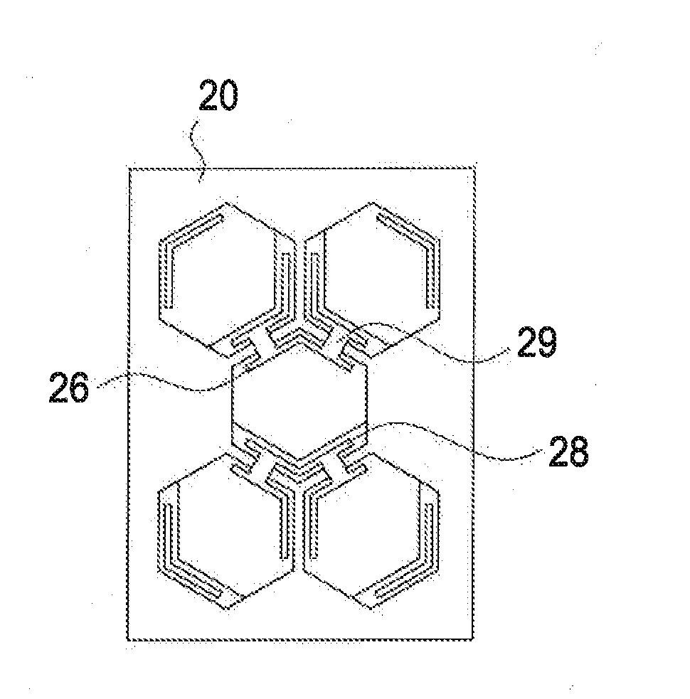
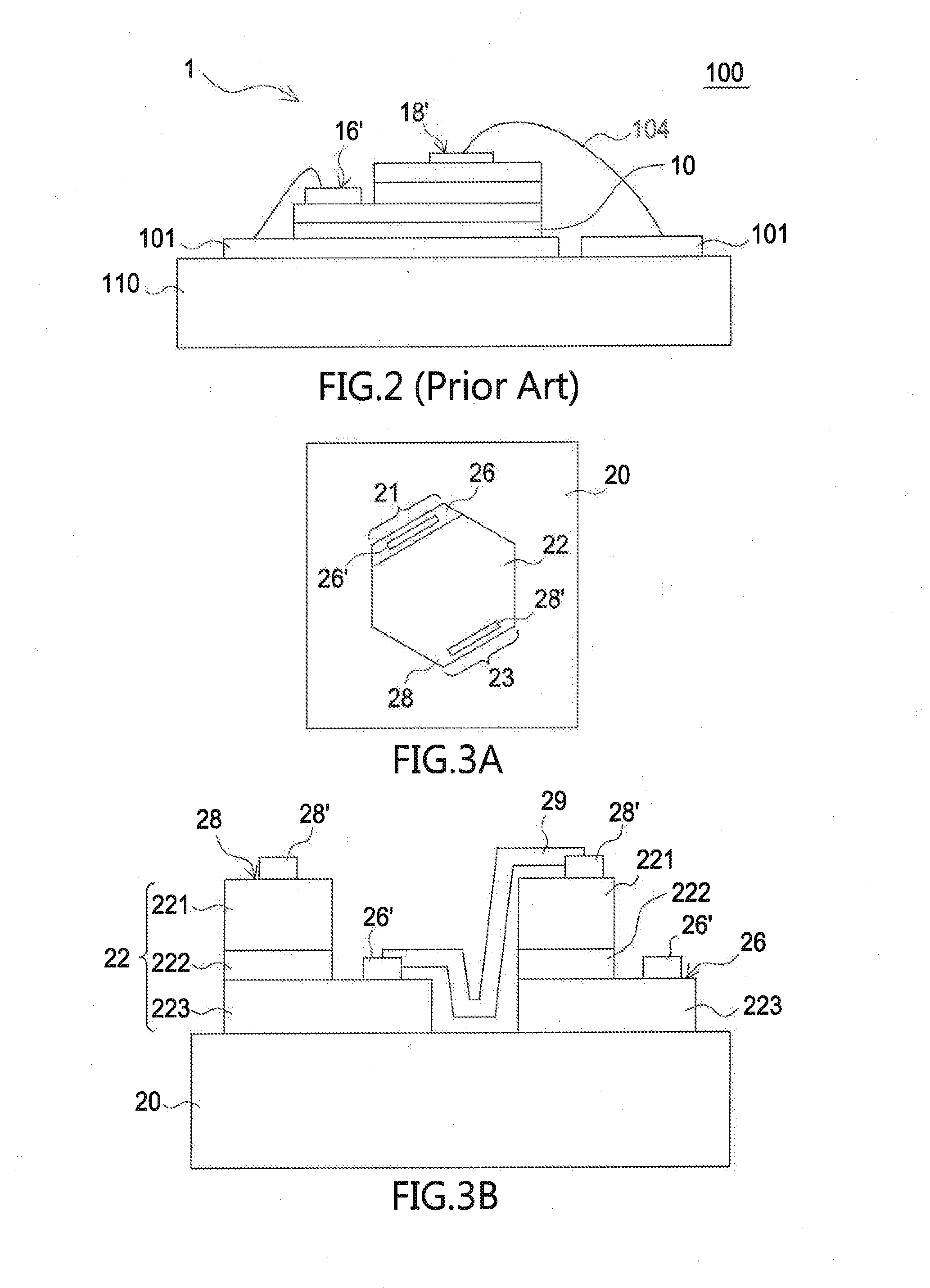
[0023]FIGS. 3A and 3B illustrate the structures of a light-emitting diode unit 22 in accordance with an embodiment of the present application. The light-emitting diode unit 22 is an equilateral hexagon formed on the substrate 20. The light-emitting diode unit 22 includes a first type semiconductor layer 223, for example, an n-type semiconductor layer; a light-emitting layer 222; a second type semiconductor layer 221, for example, a p-type semiconductor layer; a first electrical connecting area 26; and a second electrical connecting area 28. Wherein, the n-type semiconductor layer 223 of the light-emitting diode unit 22 includes a first electrical connecting area 26 disposed along a first side and the p-type semiconductor layer 221 of the light-emitting diode unit 22 includes a second e...


PUM


Abstract

A light-emitting diode device is disclosed, which includes a substrate; a plurality of light-emitting diode units, each of the light-emitting diode units being an equilateral polygon with more than four sides, are disposed on the substrate; wherein each of the light-emitting diode units includes a first electrical connecting area disposed along a first side of the light-emitting diode unit, a second electrical connecting area disposed along a second side of the light-emitting diode unit, and a conductive connecting structure disposed on each of the electrical connecting areas; wherein each of the electrical connecting area electrically connects to one another light-emitting diode unit through the conductive connecting structure.

Description

TECHNICAL FIELD[0001]The application relates to a light-emitting diode device, and more particularly, to a light-emitting diode device emitting light uniformly and having a high reliability. The light-emitting diode device comprises the structure with a plurality of light-emitting diode units formed on a single substrate.REFERENCE TO RELATED APPLICATION[0002]This application claims the right of priority based on TW application Serial No. 101127689, filed on Jul. 31, 2012, and the content of which is hereby incorporated by reference in its entirety.DESCRIPTION OF BACKGROUND ART[0003]The lighting theory and structure of light-emitting diode (LED) is different from that of conventional lighting source. An LED has advantages like low power loss, long life-time, no need for warming time, and fast responsive time. Moreover, it is small, shockproof, and suitable for mass production so LEDs are widely adopted in the market. For example, LEDs can be used in optical display apparatus, laser d...

Claims


Application Information

Patent Timeline
IPC IPC(8): H01L33/08
CPCH01L33/08H01L27/153H01L33/20H01L33/62H01L2224/48091H01L2924/00014
Inventor LI, HSIEN WEI
Owner EPISTAR CORP
Why Eureka
Try Eureka