X-ray ct apparatus

Active Publication Date: 2014-02-06
TOSHIBA MEDICAL SYST CORP
View PDF6 Cites 1 Cited by
  • Summary
  • Abstract
  • Description
  • Claims
  • Application Information

AI Technical Summary

Benefits of technology

The present X-ray CT apparatus rotates an X-ray tube and an X-ray detector around a subject to capture images of the subject by radiating X-rays and detecting them using the detector. The detector has two ranges, with one range having small detection elements and the other range having larger detection elements. The apparatus includes a control unit that can select either the small or large detection range. The technical effect is to improve image quality and accuracy of X-ray CT images by using a detector with different detection ranges optimized for detecting X-rays from the X-ray tube.

Problems solved by technology

High resolution cannot be acquired upon imaging by detecting the X-rays radiated from the focal point of the small focal point size and transmitted through the subject with the X-ray detection elements of the large detector size, making it impossible to fully utilize the X-ray detection elements of the small detector size.

Method used


Image

  • X-ray ct apparatus
  • X-ray ct apparatus
  • X-ray ct apparatus

Examples


first embodiment

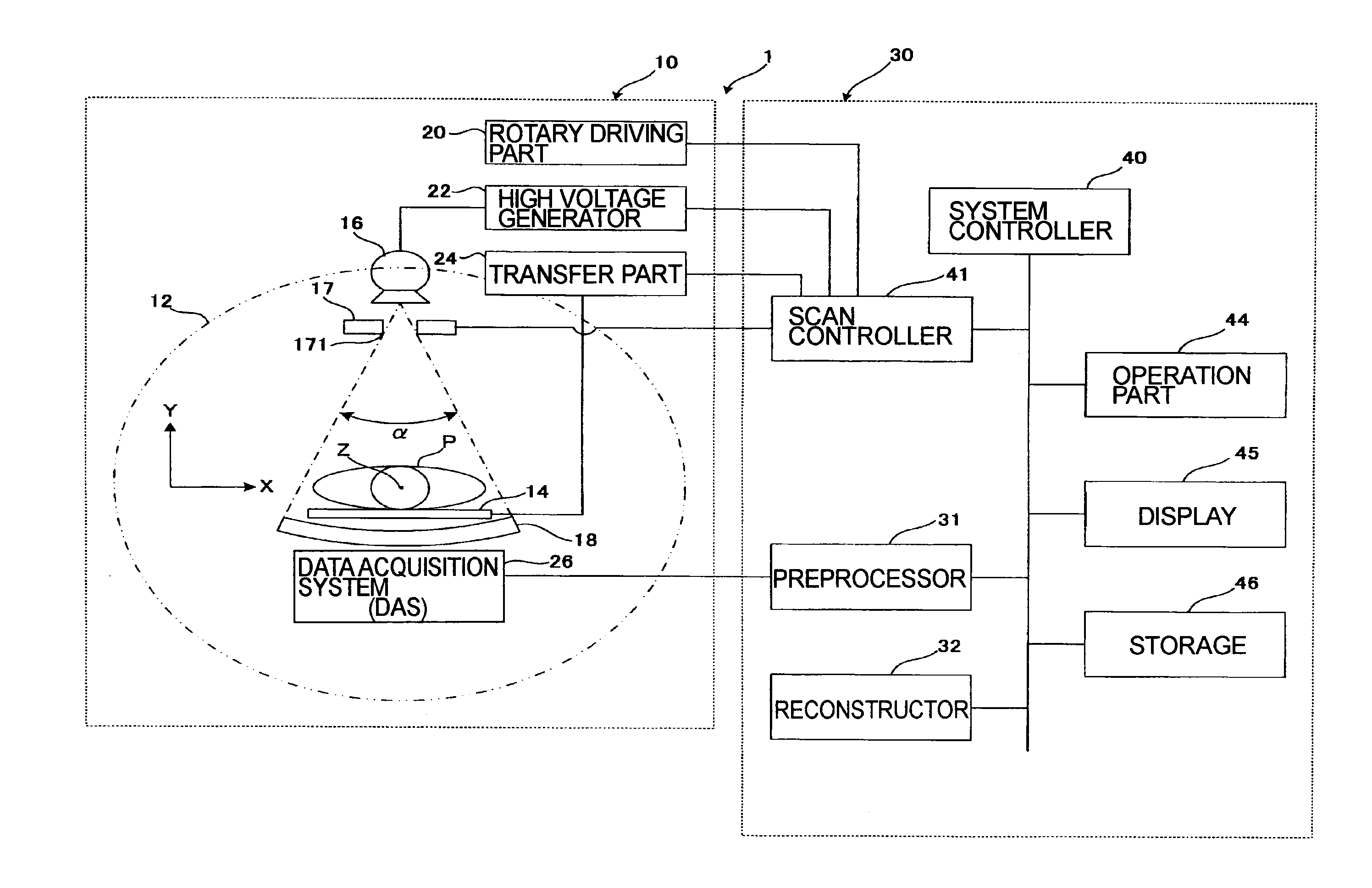
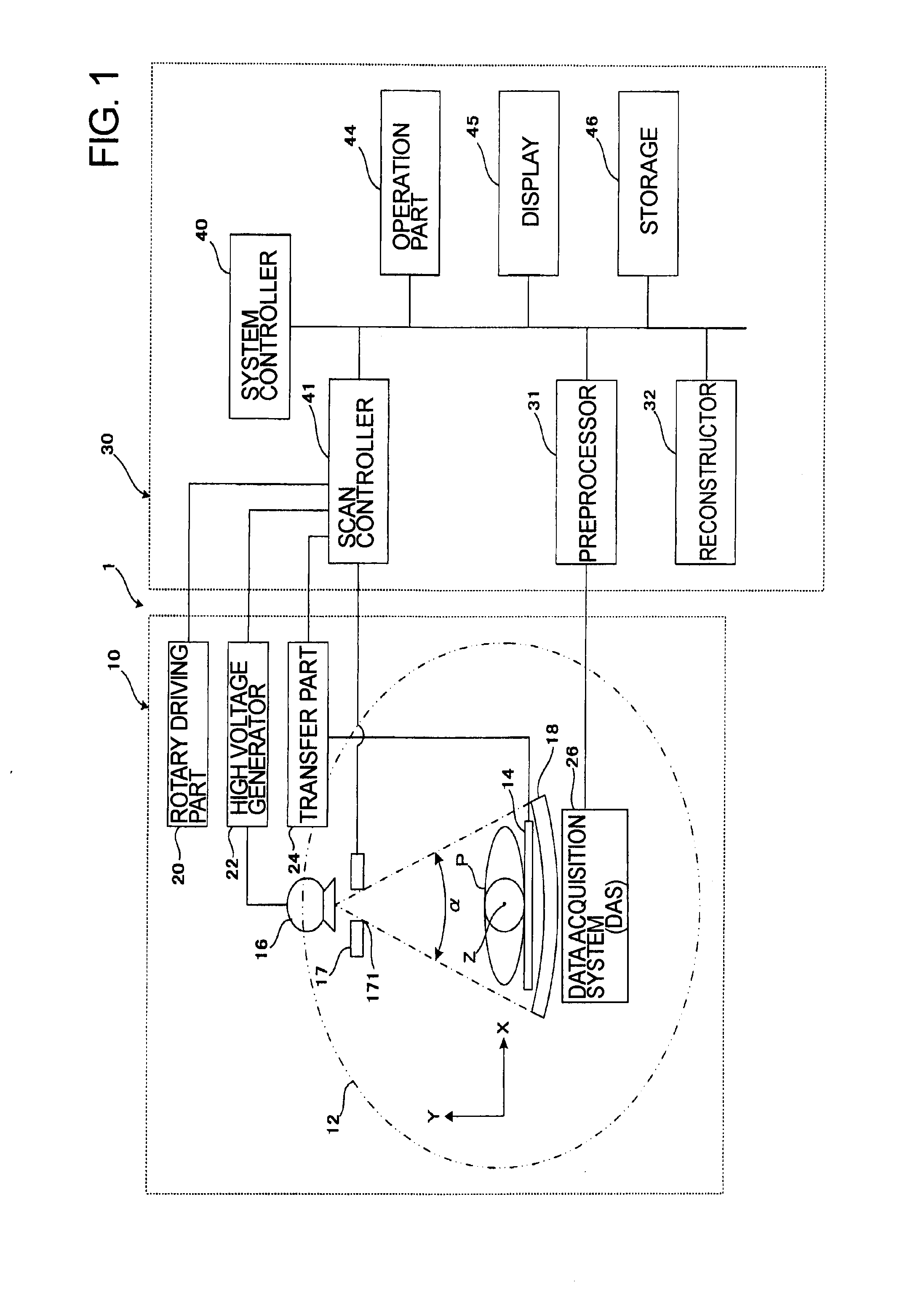
[0037]A structure of an X-ray CT apparatus according to a first embodiment is described with reference to FIG. 1. FIG. 1 is a block diagram illustrating the structure of the X-ray CT apparatus.

[0038]As illustrated in FIG. 1, an X-ray CT apparatus 1 comprises a gantry 10 and a console 30.

[0039]The gantry 10 comprises a rotating frame 12, an X-ray tube 16, a collimator 17, an X-ray detector 18, a rotary driving unit 20, a high voltage generator 22, and a data acquisition system (DAS) 26.

[0040]The body of the gantry 10 rotatably supports the circular or discoid rotating frame 12. A scan region with a subject P mounted on a table top 14 to be inserted is formed on the inner circumference of the rotating frame 12.

[0041]A top transfer unit 24 is provided on a couch (not illustrated) so as to longitudinally transfer the table top 14 (in the rostrocaudal direction of the subject P). In addition, a lifting unit (illustration omitted) for vertically sliding the table top 14 is arranged on the...

second embodiment

[0090]In the above first embodiment, the X-ray detector 18 provided with the small detection range 181 at one end in the rostrocaudal direction (Z direction) is described, while the focal point F1 of small focal point size is allowed corresponding to the small detection range 181. Thereby, it becomes possible to achieve high resolution upon imaging. In addition, as the comparative example, the X-ray detector 18 of a hybrid type in which the small detection range 181 is provided in the center in the rostrocaudal direction is described, while the focal point F3 of the middle focal point size is allowed corresponding to the small detection range 181. Thereby, high resolution cannot be obtained upon imaging.

[0091]The X-ray detector 18 of a hybrid type according to the comparative example illustrated in FIG. 7 is fixed to the rotating frame 12 so as not to transfer. However, in even such the X-ray detector 18 of a hybrid type, in order to achieve high resolution upon imaging, the X-ray d...

third embodiment

[0105]The uniform type of X-ray detector 18 illustrated in FIG. 6 is entirely configured by the large detection range 182 so that the detector size of the X-ray detection elements corresponding to the focal point F1 of the small focal point size becomes large. Therefore, high resolution cannot be achieved upon imaging. On the contrary, it becomes possible to make the detector size smaller by tilting the X-ray detector 18 with respect to the X-ray tube 16.

[0106]Further, a third embodiment is described assuming that the X-ray CT apparatus 1 includes the uniform type of X-ray detector 18; however, it is obvious that the hybrid type of X-ray detector 18 may be used instead. In other words, it becomes possible to make the detector size of the small detection range 181 smaller by tilting the small detection range 181 with respect to the X-ray tube 16.

[0107]Next, the X-ray CT apparatus according to the third embodiment is described with reference to FIG. 10 to FIG. 12. In the third embodim...


PUM


Abstract

An X-ray CT apparatus includes an X-ray tube, an X-ray detector, and a control unit. The X-ray detector includes at least two divided ranges. One range includes a small detection range in which X-ray detection elements of a small size for detecting the X-rays radiated from the X-ray tube are arrayed. The other range includes a large detection range in which the X-ray detection elements of a large size for detecting the X-rays radiated from the X-ray tube are arrayed. The control unit is configured to select the small detection range or the large detection range. The X-ray CT apparatus can efficiently achieve high resolution upon imaging and, further, is capable of fully utilizing X-ray detection elements of a small detector size.

Description

FIELD OF THE INVENTION[0001]The embodiments of the present invention relate to an X-ray CT apparatus.BACKGROUND ART [0002]Some conventional X-ray CT (computed tomography) systems detect X-rays radiated from an X-ray tube to a subject and transmitted through the subject with an X-ray detector, acquire projection data, then reconstruct images from the acquired projection data (for example, Patent Document 1.)[0003]The X-ray tube includes an anode provided with a radiation surface for radiating X-rays, as well as a cathode provided with a filament. X-rays with a cone angle enlarging from the radiation surface in the rostrocaudal direction of the subject are radiated to the subject. The size of an effective focal point, which is the apparent size when seeing the radiation surface from the side on which the X-rays are radiated, is sometimes referred to as a focal point size.[0004]The focal point size differs depending on whether seeing the radiation surface from the anode side or the cat...

Claims


Application Information

Patent Timeline
IPC IPC(8): A61B6/03
CPCA61B6/032A61B6/4266A61B6/06
Inventor TSUKAGOSHI, SHINSUKESUZUKI, TATSURO
Owner TOSHIBA MEDICAL SYST CORP
Why Eureka
Try Eureka