Al technical title is built by PatSnap Al team. It summarizes the technical point description of the patent document.
a technology of lateral cage and lateral cage, which is applied in the field of spinal implant system and method, can solve the problems of loss of height in the affected disk space, inability to stabilize the spinal column, and more susceptible to horizontal displacement of the vertebrae, so as to facilitate the removal of instruments and reduce the disturbance of soft tissu
Active Publication Date: 2014-02-06
BEACON BIOMEDICAL
View PDF4 Cites 67 Cited by
Summary
Abstract
Description
Claims
Application Information
AI Technical Summary
This helps you quickly interpret patents by identifying the three key elements:
Problems solved by technology
Method used
Benefits of technology
[0013]It is still a further objective of the present invention to provide a unique procedure to insert an interbody spacer between the L-2 and S-1 by employing an optimal angle for insertion which would enable insertion of the interbody spacer with minimal disturbance of soft tissue.
Problems solved by technology
The degeneration of the intervertebral disk, in particular, the degeneration of the nucleus pulposus, results in a loss of height in the affected disk space which is associated with a weakening of the annulus fibrosus and of the ligaments.
As a consequence, the spinal column becomes instable and is more susceptible to horizontal displacement of the vertebral bodies with respect to one another.
This horizontal movement of the vertebral bodies results in impairments of the nerve roots in this region and / or of the spinal marrow, and in pain resulting from these impairments.
Further, a PLF does not provide sufficient access to the disc space for comprehensive evacuation of the disc.
Traditional TLIF procedures do, however, suffer from shortcomings.
This two step insertion of the spacer is generally recognized among surgeons as cumbersome.
The problem of manipulating the spacer into the disc space may be exacerbated in patients where the iliac crest must be maneuvered around to place the implant.
Method used
Image
Click on the blue label to locate the original text in one second.
Reading with bidirectional positioning of images and text.
Examples
Embodiment Construction
[0036]While the present invention is susceptible of embodiment in various forms, there is shown in the drawings and will hereinafter be described a presently preferred, albeit not limiting, embodiment with the understanding that the present disclosure is to be considered an exemplification of the present invention and is not intended to limit the invention to the specific embodiments illustrated.
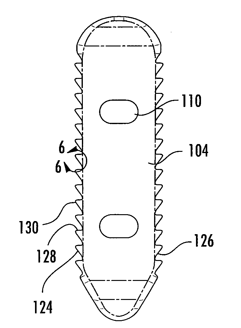
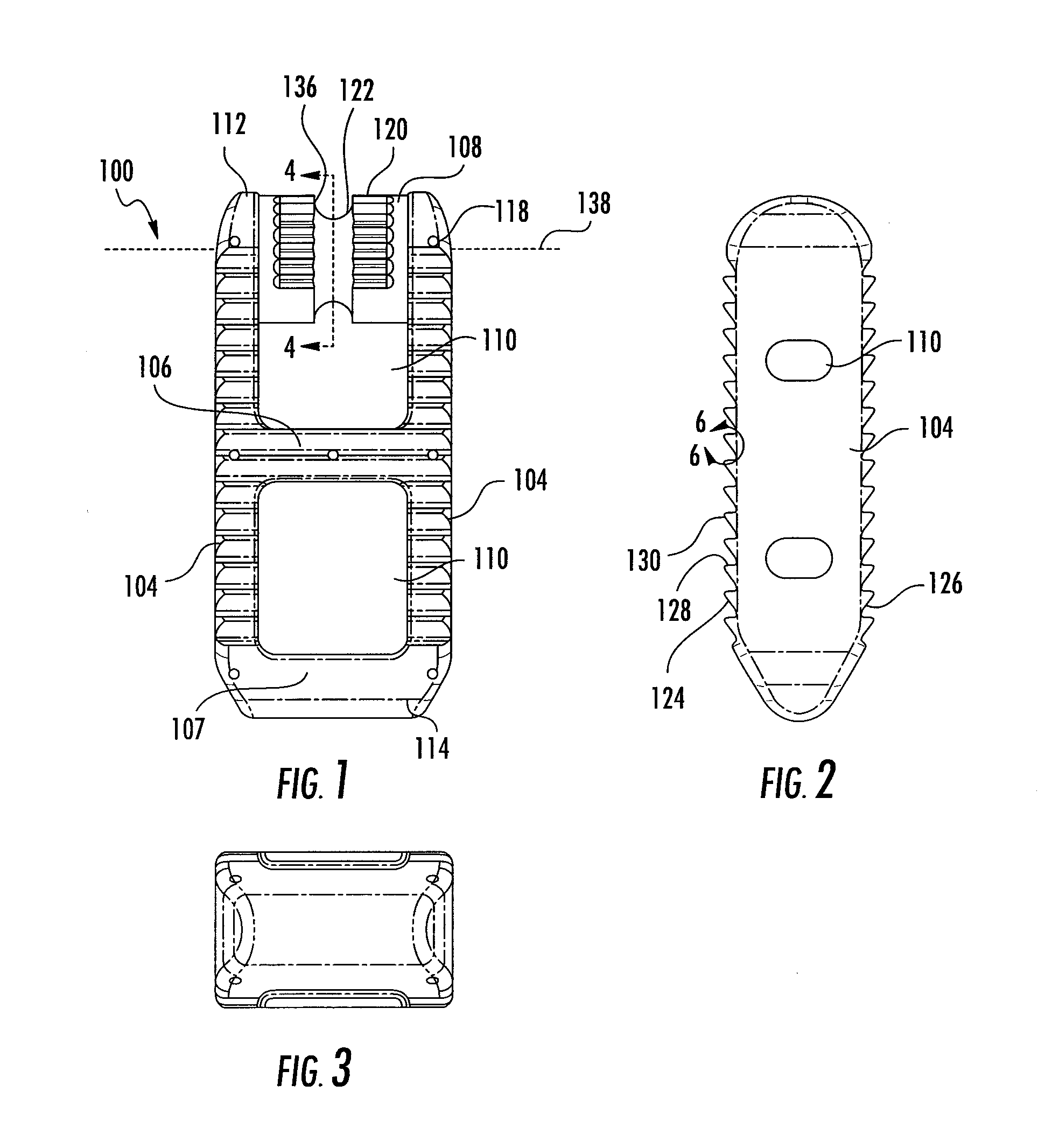
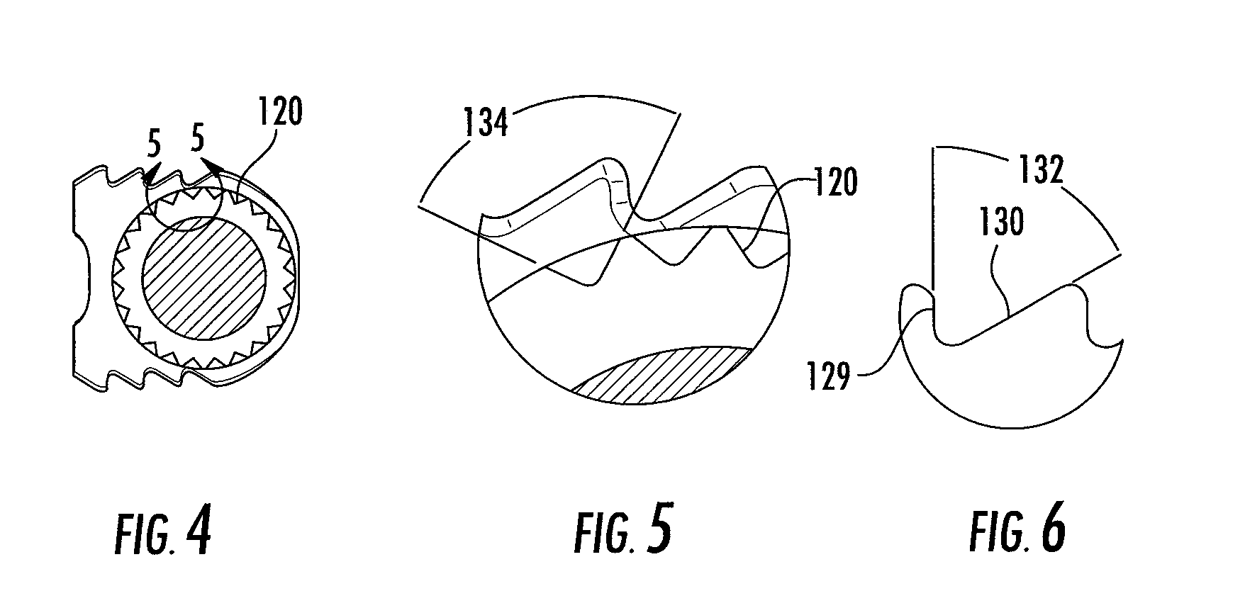
[0037]Referring to FIGS. 1-6, which are now referenced, one embodiment of the interbody spacer (100) is illustrated. As illustrated, the present exemplary interbody spacer is designed for use as an intervertebral spacer in spinal fusion surgery, where portions of an affected disc are removed from between two adjacent vertebrae 102 and replaced with an interbody spacer (100) that provides segmental stability, may correct a deformity, and allows for bone to grow between the two vertebrae to bridge the gap created by disk removal (FIG. 13).
[0038]As shown, the present exemplary interbody spacer ...
PUM
Abstract
A process for inserting a pivotable interbody spacer including an insertion instrument configured to manipulate a pivotable interbody spacer during insertion, wherein the insertion instrument includes means for coupling the interbody spacer and a means for fixing the angular position of the interbody spacer. According to one method for inserting an interbody spacer in a spinal disk space, the interbody spacer is grasped by the insertion instrument and fixed at a first angular position. The interbody spacer is next inserted into a surgical site. Next, the interbody spacer is released from a first angular position. Then, the insertion instrument is pivoted about a coupling of the interbody spacer such that the interbody spacer is in a second angular position. The angular position of the interbody spacer is then fixed in the second angular position. This insertion process continues until the interbody spacer is positioned in the desired location.
Description
CROSS REFERENCE TO RELATED APPLICATIONS[0001]In accordance with 37 C.F.R. 1.76, a claim to priority is included in the Application Data Sheet filed concurrently herewith. Accordingly, the present invention claims priority under 35 of U.S.C. 119(e) to U.S. Application Ser. No. 61 / 678,891; filed on Aug. 2, 2012, entitled, “PIVOTAL LATERAL CAGE AND METHOD OF INSERTION”. This present invention is also related to U.S. Pat. No. 7,892,239, issued Feb. 22, 2011, entitled “PIVOTABLE INTERBODY SPACER SYSTEM AND METHOD”; U.S. Pat. No. 8,043,293, issued Oct. 25, 2011, entitled “PIVOTABLE INTERBODY SPACER”; U.S. Pat. No. 8,157,845, issued Apr. 17, 2012, entitled “PIVOTABLE VERTEBRAL SPACER”; and U.S. Pat. No. 8,444,650, issued May 21, 2013, entitled “PIVOTABLE INTERBODY SPACER SYSTEM AND METHOD”, the entireties of which are incorporated herein by reference.FIELD OF THE INVENTION[0002]The present invention and method of use relate to bone fixation devices and procedures for the placement of these...
Claims
Application Information
Patent Timeline
Application Date:The date an application was filed.
Publication Date:The date a patent or application was officially published.
First Publication Date:The earliest publication date of a patent with the same application number.
Issue Date:Publication date of the patent grant document.
PCT Entry Date:The Entry date of PCT National Phase.
Estimated Expiry Date:The statutory expiry date of a patent right according to the Patent Law, and it is the longest term of protection that the patent right can achieve without the termination of the patent right due to other reasons(Term extension factor has been taken into account ).
Invalid Date:Actual expiry date is based on effective date or publication date of legal transaction data of invalid patent.
Patent Type & Authority Applications(United States)