Seismic Inversion for Formation Properties and Attentuation Effects
- Summary
- Abstract
- Description
- Claims
- Application Information
AI Technical Summary
Benefits of technology
Problems solved by technology
Method used
Image
Examples
example
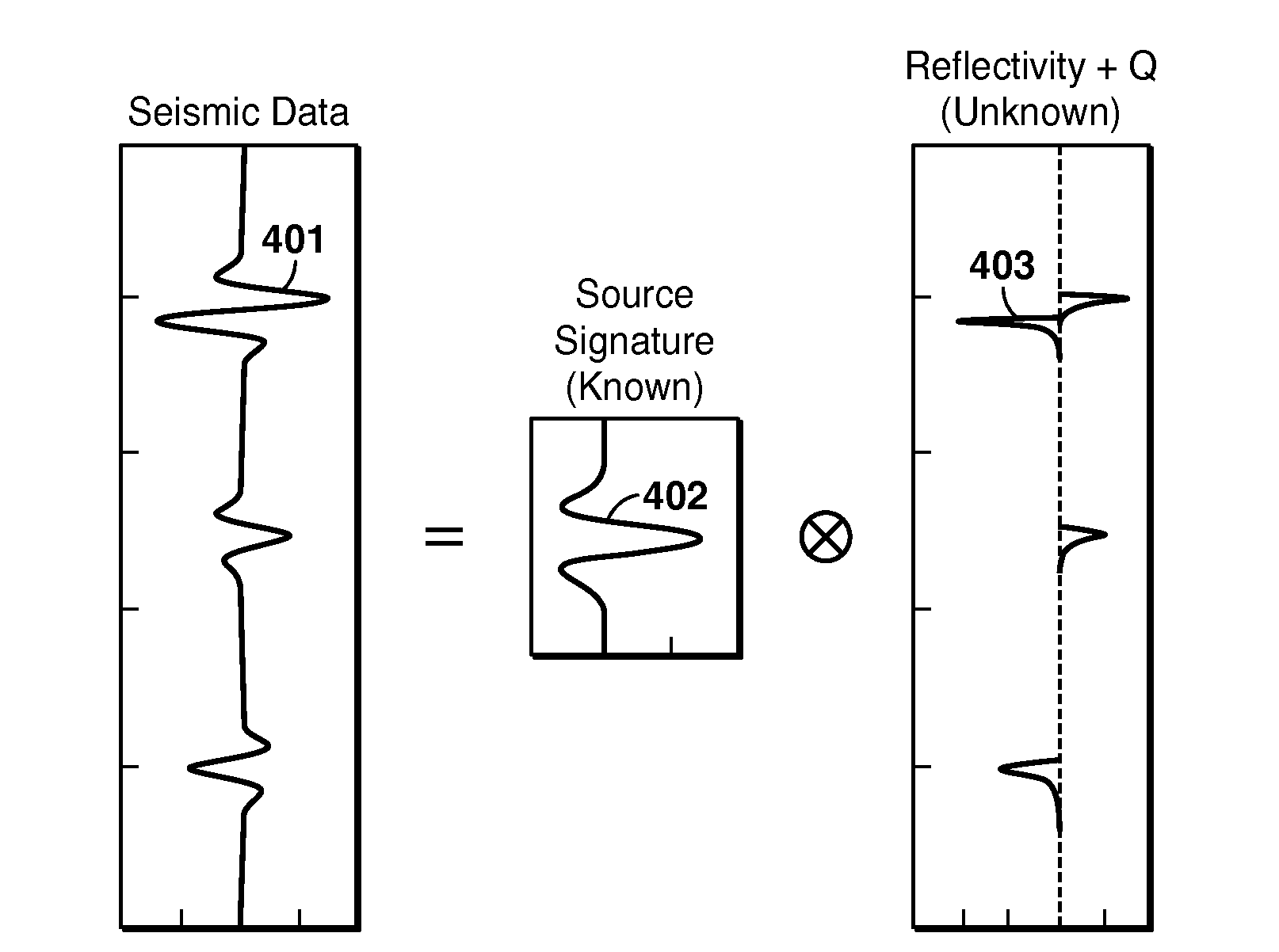
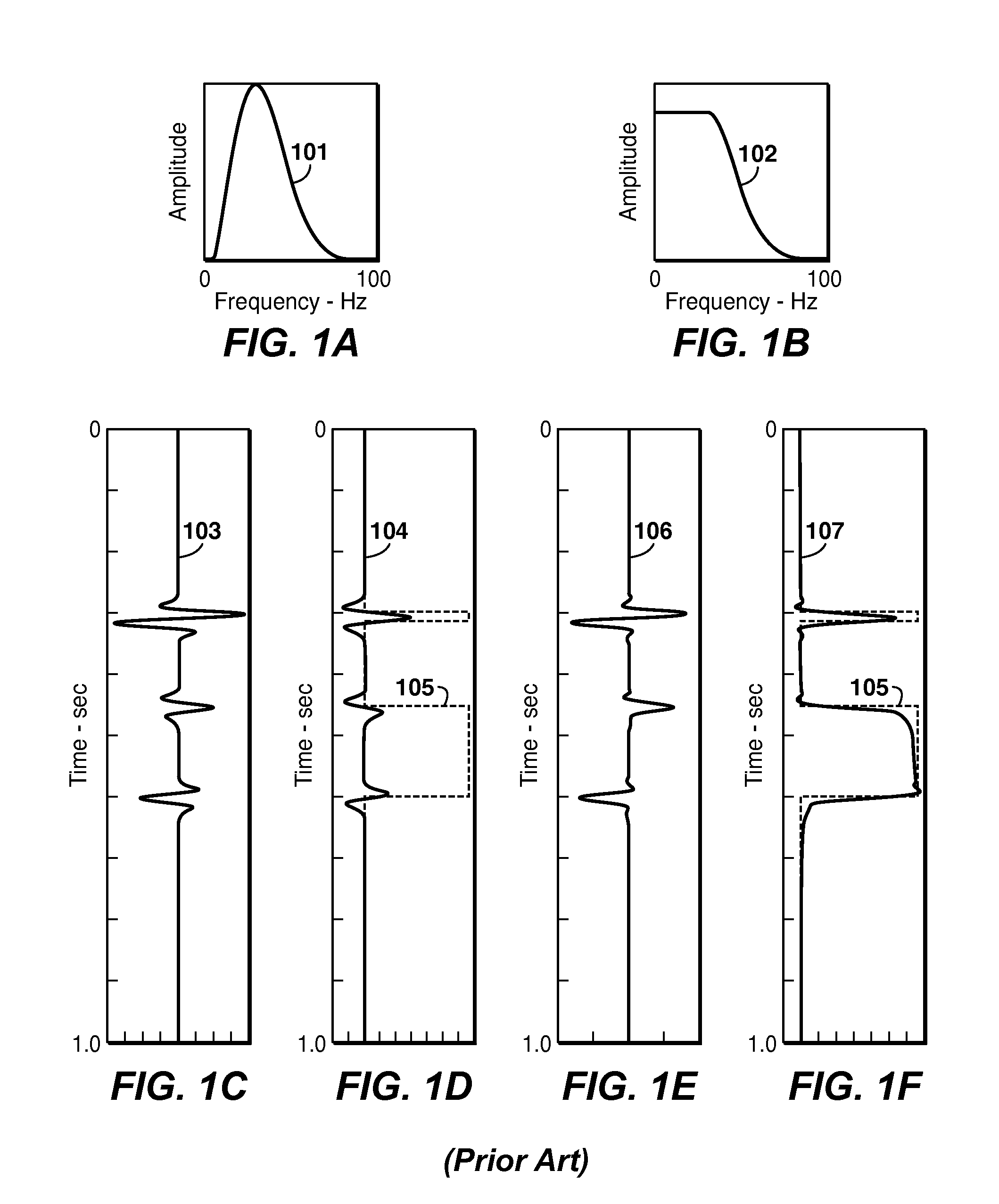
[0042]An example is shown in FIG. 6. The seismic data trace 601 is the same as shown as 103 in FIG. 1. The band-limited source signature 101 is assumed, and the data inverted for values of reflection coefficients, time delay and attenuation (1 / Q). The reflection coefficients 602 are plotted as a function of the travel time, and the attenuation 603 is also shown as a function of the travel time. Integration of 602 can be performed which yields the total impedance 604, which matches the model impedance 105. Alternatively, the forward model can be computed from 602 using the desired broad-band source signature 102, neglecting attention. This is shown as 702 in FIG. 7, and can be compared to the original trace 701. Now integration of 702 yields 703, which is a good approximation of the original impedance 105.
PUM
 Abstract
Description
Claims
Application Information
 - R&D
- Intellectual Property
- Life Sciences
- Materials
- Tech Scout
- Unparalleled Data Quality
- Higher Quality Content
- 60% Fewer Hallucinations
Browse by: Latest US Patents, China's latest patents, Technical Efficacy Thesaurus, Application Domain, Technology Topic, Popular Technical Reports.
© 2025 PatSnap. All rights reserved.Legal|Privacy policy|Modern Slavery Act Transparency Statement|Sitemap|About US| Contact US: help@patsnap.com


