Liftable hospital bed

a hospital bed and lift technology, applied in the field of hospital beds, can solve the problems of affecting rehabilitation, affecting the service life of the motor, and affecting the movement of the whole hospital bed, so as to reduce production costs, reduce the service life of the motor, and reduce the effect of motor power

Inactive Publication Date: 2014-02-13
NINGBO KANGMAILONG MEDICAL APP
View PDF5 Cites 33 Cited by
  • Summary
  • Abstract
  • Description
  • Claims
  • Application Information

AI Technical Summary

Benefits of technology

[0013]When the motor rotates to drive the turbine, the turbine drives the worm to protract or retract. A front end of the worm drives the connecting rod to turn relative to the bedplate base, so that the two sliding slots of the connecting plate at the end of the connecting rod respectively drive the two pin shafts on the bed leg rod, thereby causing the bed leg rod to turn. Because the upper end of the bed leg rod can move in the bedplate base in a longitudinal direction, and because of the special hinge structure between the bed leg rod and the connecting rod, a hinge point between the bed leg rod and the connecting rod moves in the sliding slot, which compensates the longitudinal displacement of the ground-touching end of the bed leg rod during standing uprightly

Problems solved by technology

This results in the movement of the whole hospital bed.
This phenomenon generally makes a patient uncomfortable.
Especially for a critically ill person whose body is full of various cannulas, dragging caused by the movement of the hospital bed may le

Method used


Image

  • Liftable hospital bed
  • Liftable hospital bed
  • Liftable hospital bed

Examples


Embodiment Construction

[0025]The present invention is further described below with reference to the accompanying drawings. Referring to the drawings:

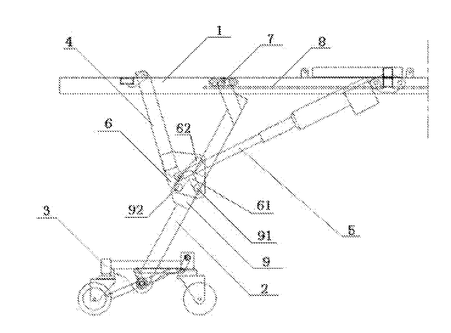
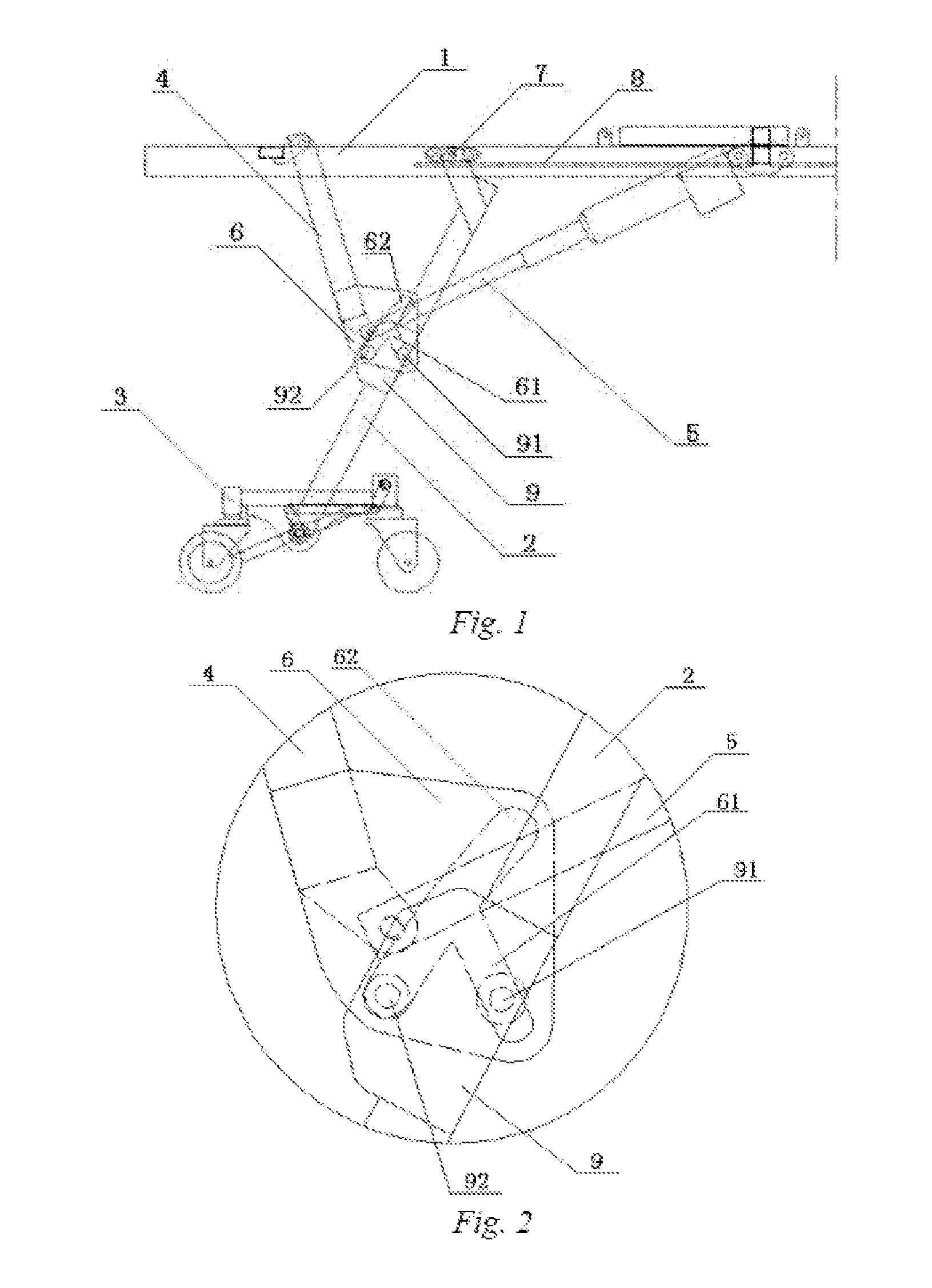
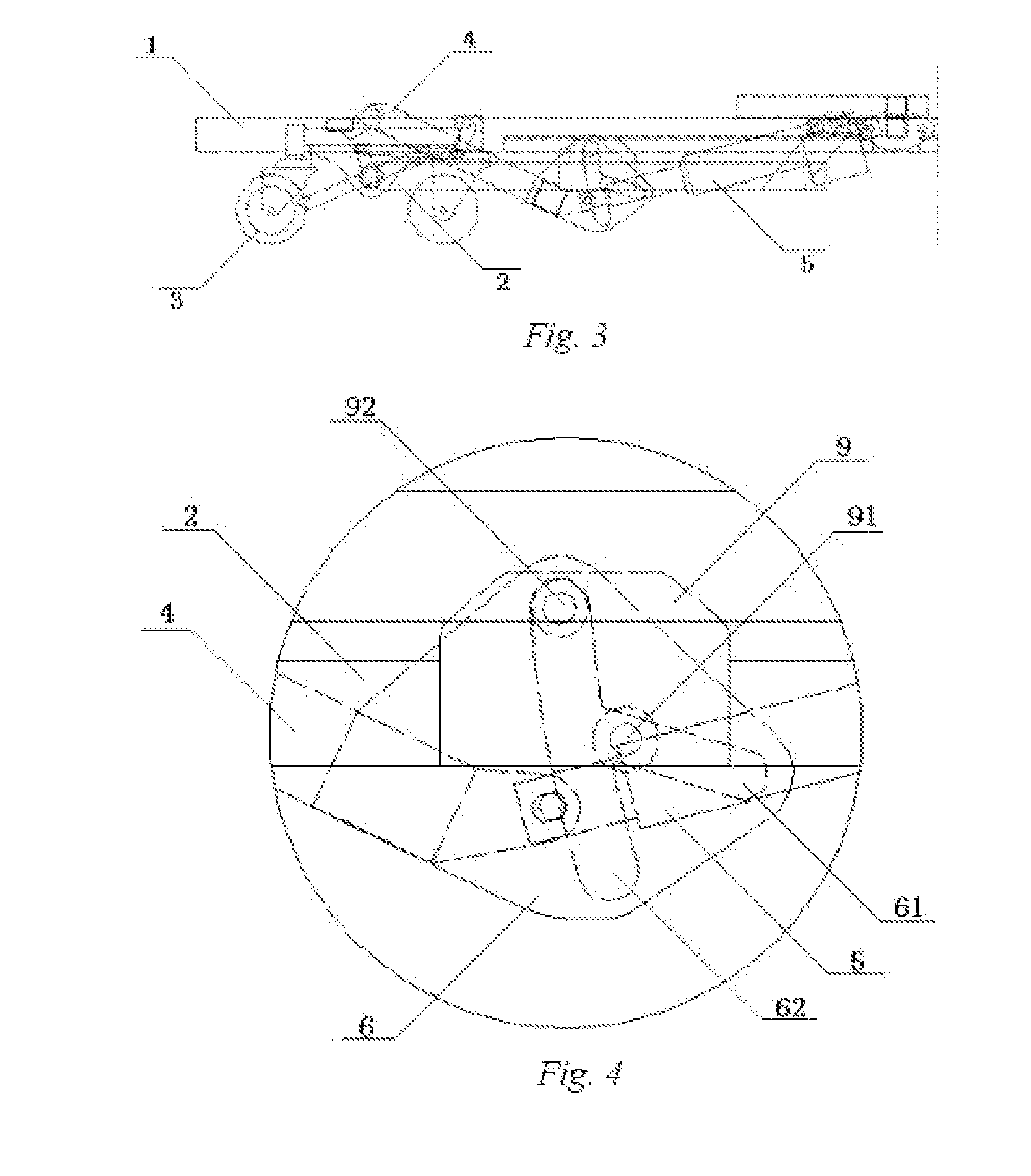
[0026]A liftable hospital bed according to the present invention comprises a bedplate base 1. Said bedplate base 1 is supported by bed leg rods 2 symmetrically located on the two sides of said bedplate base, and a bottom end of said bed leg rod 2 is hinged to a first roller device 3 touching the ground.

[0027]An upper end of said bed leg rod is connected to a second roller device 7. Said second roller device 7 can slide in a track 8 on said bedplate base 1, and said track 8 is parallel to a longitudinal axis of said bedplate base 1.

[0028]A turning mechanism is further provided to change the included angle between said bed leg rod 2 and said bedplate base 1 in order to lift or lower the bedplate base 1. Said turning mechanism includes a connecting rod 4 which is hinged at the upper end thereof to said bedplate base, and a pushing mechanism 5. A lower end of sai...


PUM


Abstract

A liftable hospital bed, comprising a bedplate base (1) and a bed leg rod (2), the upper end of the bed leg rod (2) being connected to a second roller device (7) which can slide in a track (8) on the bedplate base (1); a turning mechanism is also provided to change the included angle between the bed leg rod (2) and the bedplate base (1) in order to lift or lower the bedplate base (1), the turning mechanism including a connecting rod, which is hinged at the upper end thereof to the bedplate base (1), and a pushing mechanism (5) for pushing and turning the connecting rod (4); the lower end of the connecting rod (4) is fixedly bonded to a first connecting plate (6) which has a first sliding slot (61) and a second sliding slot (62) crossed with each other; a first pin shaft (91) and a second pin shaft (92) on the bed leg rod (2) are slidably provided in the first sliding slot (61) and the second sliding slot (62). During lifting, the ground-touching end of the bed leg rod (2) can be maintained unmoved, so as to prevent the movement of the patient's body.

Description

(I) TECHNICAL FIELD[0001]The present invention relates to a hospital bed.(II) BACKGROUND ART[0002]A common hinge structure is used between a connecting rod and a bed leg rod of an existing hospital bed, where the longitudinal displacement of the bed leg rod during the folding and stretching thereof cannot be compensated, and the longitudinal position of a ground-touching end of the bed leg rod relative to the hospital bed will be changed. This results in the movement of the whole hospital bed. Because a hospital bed is always placed with one end pressing against a wall, bed legs away from the wall are normally forced to move backwards, with continuous vibration. This phenomenon generally makes a patient uncomfortable. Especially for a critically ill person whose body is full of various cannulas, dragging caused by the movement of the hospital bed may lead to serious consequences and affect the rehabilitation. However, for various reasons, the hospital bed must be able to be lifted a...

Claims


Application Information

Patent Timeline
IPC IPC(8): A61G7/012
CPCA61G7/012
Inventor LI, LUPING
Owner NINGBO KANGMAILONG MEDICAL APP
Why Eureka
Try Eureka