Liquid crystal display device

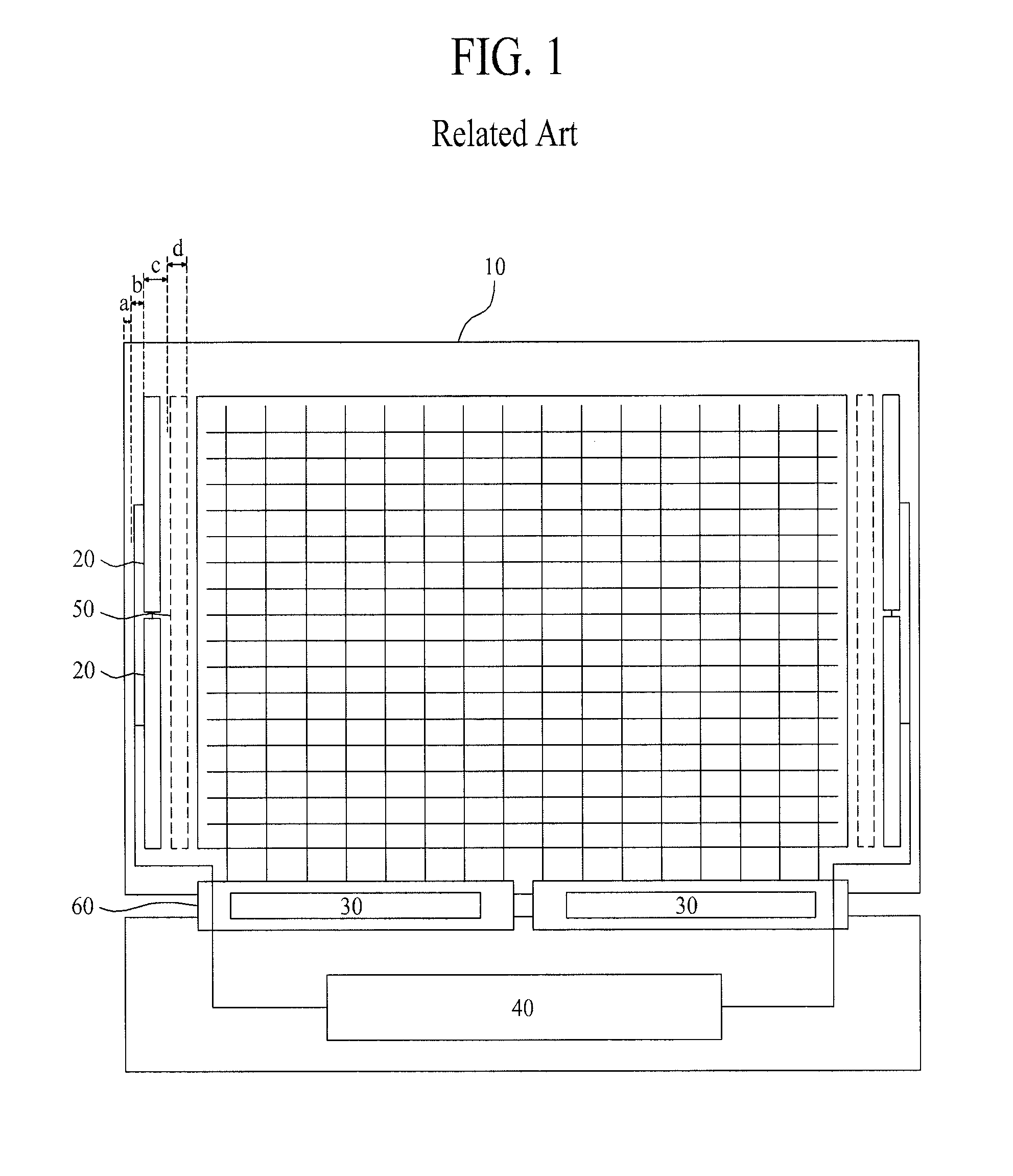
a display device and liquid crystal technology, applied in the field of display devices, can solve the problems of reducing the size of the gip circuit area “c” and the gip signal area “b” formed for applying a signal to a gip, and the method of reducing the ground and scribe area “a” or the gip signal area “b” has a limitation

Active Publication Date: 2014-02-13
LG DISPLAY CO LTD
View PDF4 Cites 82 Cited by
  • Summary
  • Abstract
  • Description
  • Claims
  • Application Information

AI Technical Summary

Benefits of technology

[0016]Accordingly, one object of the present invention is to provide an LCD device with a narrow bezel and a driving method thereof that substantially obviate one or more problems due to limitations and disadvantages of the related art.

Problems solved by technology

However, a method of reducing the size of the GIP circuit area “c” has a limitation.
However, when the Vcom area 50“d” decreases, factors which degrade quality of the LCD device like horizontal crosstalk occur.
Moreover, a method that reduces the ground and scribe area “a” or the GIP signal area “b” formed for applying a signal to a GIP has a limitation.

Method used


Image

  • Liquid crystal display device
  • Liquid crystal display device
  • Liquid crystal display device

Examples


Embodiment Construction

[0029]Reference will now be made in detail to the embodiments of the present invention, examples of which are illustrated in the accompanying drawings. Wherever possible, the same reference numbers will be used throughout the drawings to refer to the same or like parts. Hereinafter, embodiments of the present invention will be described in detail with reference to the accompanying drawings.

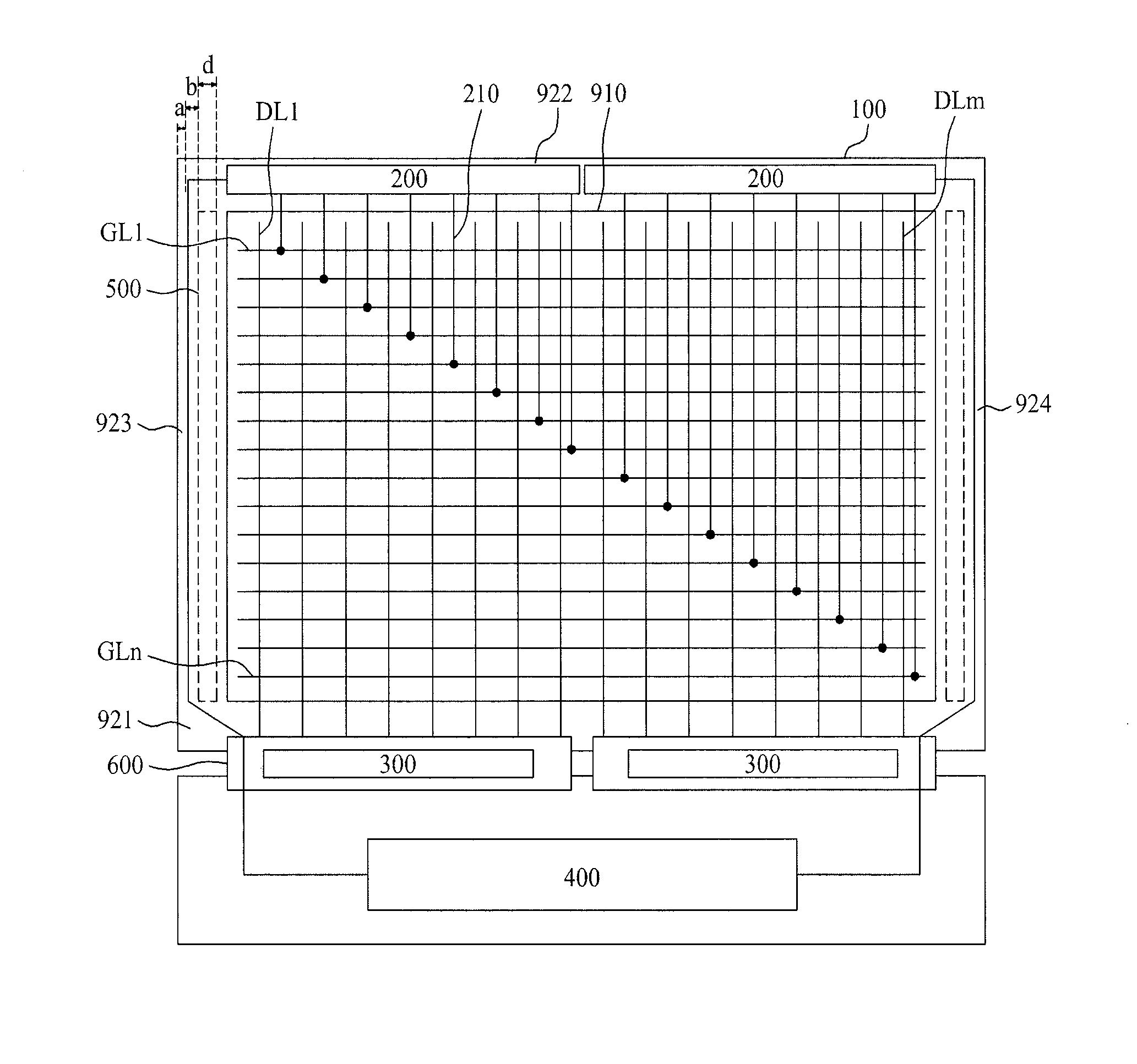
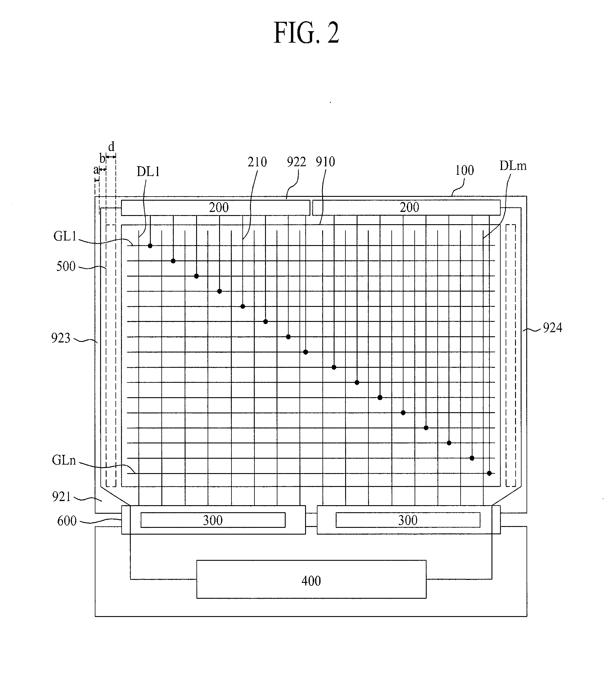
[0030]FIG. 2 is a configuration diagram illustrating an LCD device according to one embodiment of the present invention. Further, FIG. 3 is a diagram illustrating a configuration of a panel of an LCD device according to an embodiment of the present invention, and illustrates the panel driven in a double rate driving (DRD) type.

[0031]As shown in FIG. 2, the LCD device includes a panel 100 that has a display area 910 and four non-display areas 921 to 924 formed at an outer portion of the display area 910; a data driver 300 disposed in the first non-display area 921 for driving a plurality of data li...


PUM


Abstract

A display device including a panel having a display area and first, second, third and fourth non-display areas formed at an outer portion of the display area, said first non-display area facing the second non-display area, and the third non-display area facing the fourth non-display area; a data driver disposed in the first non-display area, and configured to drive a plurality of data lines provided in a first direction in the display area; a gate driver disposed in the second non-display area and configured to drive a plurality of gate lines provided in a second direction vertical to the first direction in the display area; a timing controller configured to drive the data driver and the gate driver; and a plurality of link lines in the display area and extending from the gate driver and provided in parallel to the data lines respectively connected to the gate lines.

Description

CROSS-REFERENCE TO RELATED APPLICATIONS[0001]This application claims the benefit of the Korean Patent Application Nos. 10-2012-0087817 and 10-2012-0087857 both filed on Aug. 10, 2012, which are hereby incorporated by reference as if fully set forth herein.BACKGROUND OF THE INVENTION[0002]1. Field of the Invention[0003]The present invention relates to a display device such as a liquid crystal display (LCD) device, and more particularly, to a display device with a narrow bezel and a driving method thereof.[0004]2. Discussion of the Related Art[0005]Flat panel display (FPD) devices are applied to various electronic products such as portable phones, tablet personal computers (PCs), notebook computers, etc. The FPD devices include liquid crystal display (LCD) devices, plasma display panels (PDPs), organic light emitting diode (OLED) display devices, etc. Recently, electrophoretic display (EPD) devices are widely used as FPD devices.[0006]In such FPD devices, LCD devices display an image ...

Claims


Application Information

Patent Timeline
Patent Type & Authority Applications(United States)
IPC IPC(8): G09G3/36
CPCG09G3/3685G09G3/3677G09G2300/0426G09G2310/0218G09G2310/0281G09G2320/0223
Inventor MIN, WOONG KIBAEK, HEUM SEOKSON, MI YOUNGKIM, HO JUNEPARK, YOON SANPARK, SUNG GON
Owner LG DISPLAY CO LTD
Why Eureka
Try Eureka