Edge-illumination type backlight module and liquid crystal display using the same

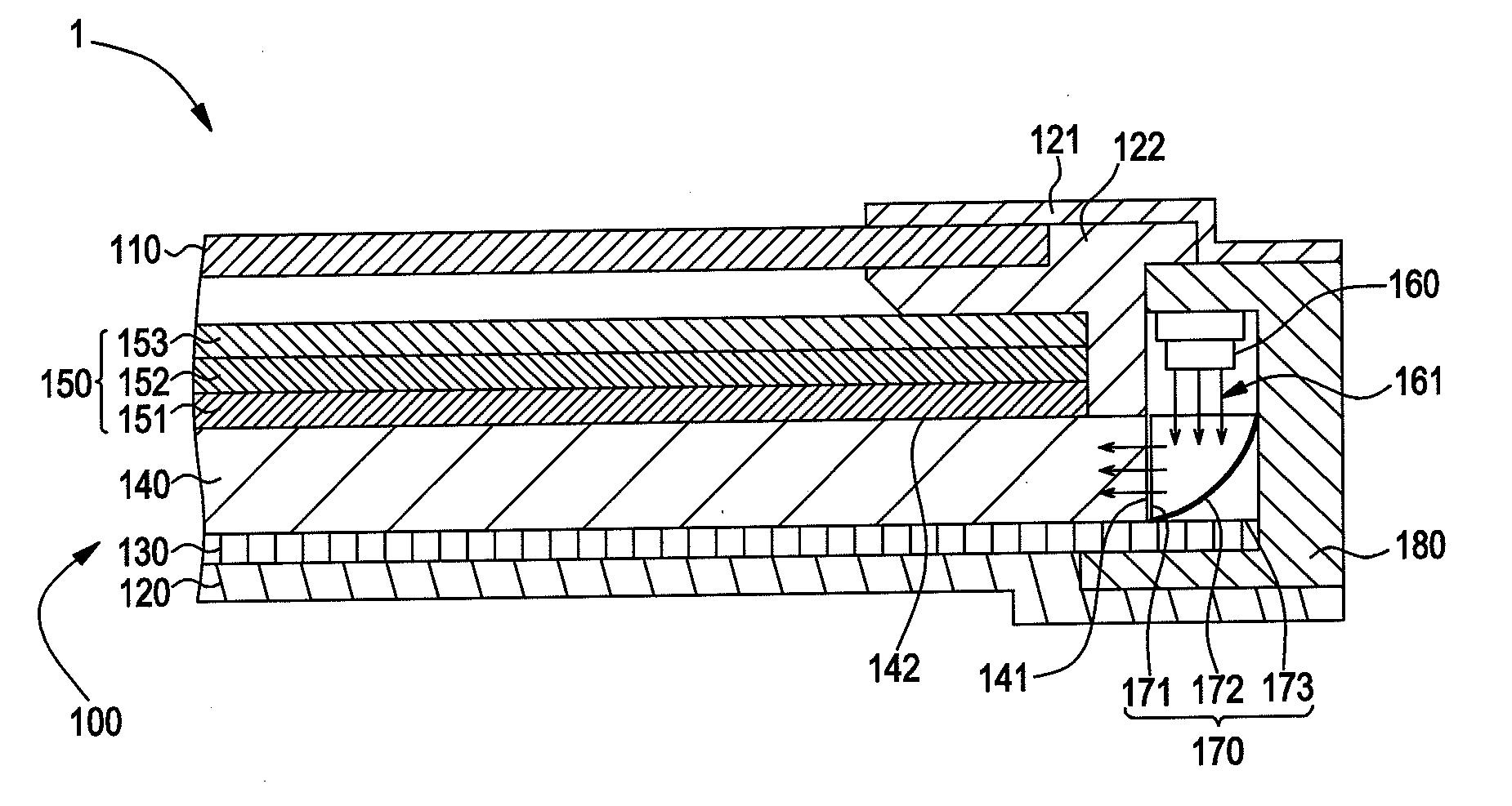
a backlight module and liquid crystal display technology, applied in the direction of planar/plate-like light guides, lighting and heating apparatus, instruments, etc., can solve the problems of the inability to project the active area of the light guide plate b>920/b>, and the inability to increase the distance a from the light emitting surface. , to achieve the effect of affecting the image quality

Active Publication Date: 2014-02-13
TCL CHINA STAR OPTOELECTRONICS TECH CO LTD
View PDF4 Cites 12 Cited by
  • Summary
  • Abstract
  • Description
  • Claims
  • Application Information

AI Technical Summary

Benefits of technology

[0007]One objective of the present invention is to overcome the drawback of hot spot appearances produced on the optical films in the light source of the conventional edge-illumination type backlight module, such that a novel edge-illumination type backlight module is provided. The edge-illumination type backlight module according to the present invention can solve the problem caused by a short distance between a light emitting surface of a light source device and a light guide plate, which may generate a non-illumination at the local area of the light guide plate seriously affecting image qualities.
[0008]Another objective of the present invention is to overcome the drawback of hot spot appearances produced on the optical films in the light source of the conventional edge-illumination type backlight module of a liquid crystal, such that an edge-illumination type backlight module is provided. The novel liquid crystal display according to the present invention can solve the problem caused by a short distance between a light emitting surface of a light source device and a light guide plate, which may generate a non-illumination at the local area of the light guide plate seriously affecting image qualities.
[0019]As the foregoing, the edge-illumination type backlight module and the liquid crystal display using the same have an advantageous effect in that a distance between the light emitting surface of the LED and the light entrance surface of the light guide plate can be increased by using the light guide bar; moreover, cooperating with the reflective surface having an arc or inclined surface in the light guide bar, an illumination of the light source become more uniformly distributed into the light guide plate, so as to prevent the hot spot appearance from being produced.

Problems solved by technology

Otherwise, when A / P ration is lower, the image quality is poor.
However, under a situation without reducing the active area 930 of the display panel, the distance A from the light emitting surface of the LED 910 to the active area 930 projected on the light guide plate 920 cannot be increased due to the structure limitation in the conventional backlight module 9.
Hence, A / P ratio cannot be improved, and the image quality is decreased.

Method used


Image

  • Edge-illumination type backlight module and liquid crystal display using the same
  • Edge-illumination type backlight module and liquid crystal display using the same
  • Edge-illumination type backlight module and liquid crystal display using the same

Examples


first embodiment

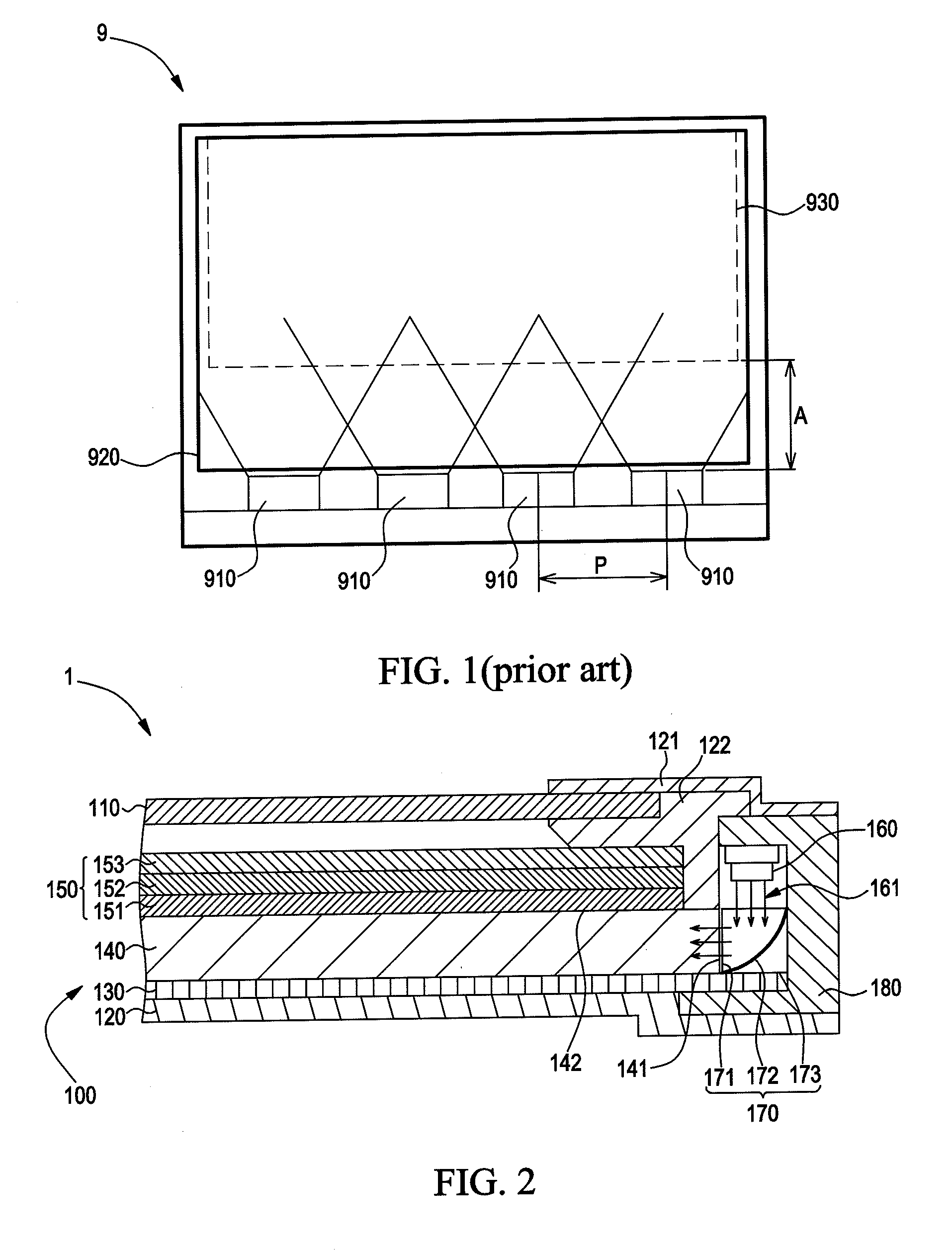
[0027]FIG. 2 illustrates a partial cross-section view of a liquid crystal display according to the present invention. As shown in FIG. 2, a liquid crystal display 1 comprises a liquid crystal panel 110, an edge-illumination type backlight module 100, a back cover 120, a front frame 121, and a middle bezel 122.

[0028]The edge-illumination type backlight module 100 is disposed on the back cover 120, and the middle bezel 122 is disposed on the edge-illumination type backlight module 100. That is, the edge-illumination type backlight module 100 is disposed between the middle bezel 122 and a back cover 120. The liquid crystal panel 110 is disposed on the edge-illumination type backlight module 100, the middle bezel 122 is disposed between the edge-illumination type backlight module 100 and the liquid crystal panel 110, and the front frame 121 is disposed on the liquid crystal panel 110. That is, the liquid crystal panel 110 is disposed between the front frame 121 and the middle bezel 122....

third embodiment

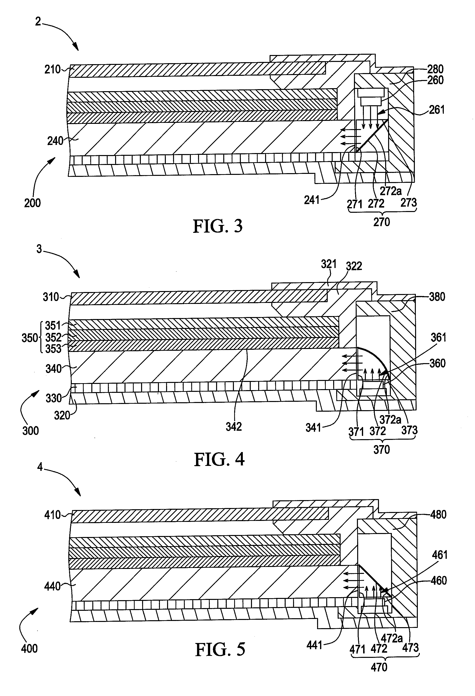
[0038]FIG. 4 illustrates a cross-section of a partial liquid crystal display according to the present invention. As shown in FIG. 4, the liquid crystal display 3 comprises a liquid crystal panel 310, an edge-illumination type backlight module 300, a back cover 320, a front frame 321, and a middle bezel 322.

[0039]The edge-illumination type backlight module 300 is disposed on the back cover 320, and the middle bezel 322 is disposed on the edge-illumination type backlight module 300. That is, the edge-illumination type backlight module 300 is disposed between the middle bezel 322 and the back cover 320. The liquid crystal panel 310 is disposed on the edge-illumination type backlight module 300, the middle bezel 322 is disposed between the edge-illumination type backlight module 300 and the liquid crystal panel 310, and the front frame 321 is disposed on the liquid crystal panel 310. That is, the liquid crystal panel 310 is disposed between the front frame 321 and the middle bezel 322. ...


PUM


Abstract

Providing is an edge-illumination type backlight module, comprising a light guide bar comprising a light incident surface and a light exiting surface; a light source device for emitting a light to the light incident surface; a light guide plate comprising a light emitting surface and a light entrance surface, wherein the light emitting surface is disposed on a surface of the light guide plate, the light entrance surface is disposed at a lateral surface of the light guide plate, the light guide plate is adjacent to the light guide bar, the light exiting surface of the light guide bar faces to the light entrance surface of the light guide plate, and the light emitting surface of the light guide plate is vertical to a light emitting direction of the light source device; and an optical film disposed on the light emitting surface of the light guide plate.

Description

FIELD OF THE INVENTION[0001]The present invention relates to an edge-illumination type backlight module and a liquid crystal display using the same, and more particularly to a structure increasing the light path by a light guide bar in the backlight module.BACKGROUND OF THE INVENTION[0002]In a liquid crystal display, because the liquid crystal itself cannot emit light, a backlight module is used to provide a uniform light source with enough illumination to the liquid crystal panel for displaying an image. Generally, the backlight module includes an edge-illumination type and a direct-illumination type, wherein a light source of the edge-illumination is disposed at a lateral side. The edge-illumination type has advantages in light-weight, compact in size, and low power consumption, such that it has usually been used as the screen of cell phones, personal digital assistants (PDA), and notebooks.[0003]Referring to FIG. 1, it illustrates a top view of a partial structure according to a ...

Claims


Application Information

Patent Timeline
Patent Type & Authority Applications(United States)
IPC IPC(8): F21V7/00F21Y105/00
CPCF21V7/00G02B6/0031G02B6/0091
Inventor ZENG, DAWEI
Owner TCL CHINA STAR OPTOELECTRONICS TECH CO LTD
Why Eureka
Try Eureka