

Terminal apparatus, base station apparatus, communication system, and communication method
a technology of base station and terminal apparatus, applied in the field of terminal apparatus, a base station apparatus, a communication system, and a communication method, can solve the problem of low frequency utilization efficiency and achieve the effect of efficient reporting of reception quality information
- Summary
- Abstract
- Description
- Claims
- Application Information
AI Technical Summary
Benefits of technology
Problems solved by technology
Method used
Image

Examples
first embodiment
[0044]Hereinafter, a first embodiment of the present invention will be described with reference to the drawings.
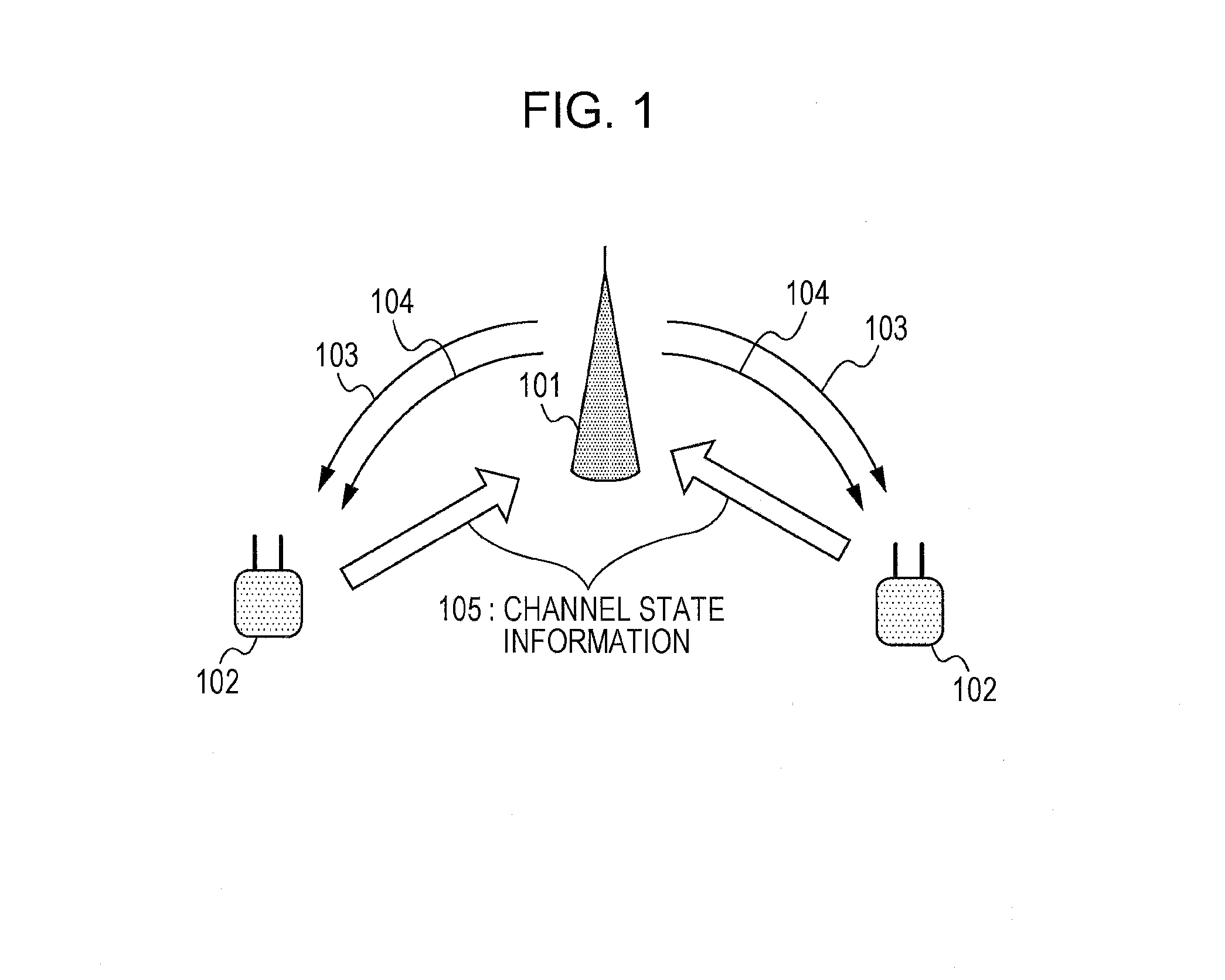
[0045]FIG. 1 is a schematic configuration diagram showing a configuration of a communication system according to the first embodiment of the present invention. The communication system of the drawing is assumed to be an LTE-A system, and includes a base station apparatus (base station, transmitter station, downlink transmitting apparatus, uplink receiving apparatus, or eNodeB) 101 which configures cells, and a terminal apparatus (mobile station apparatus, mobile station, receiver station, uplink transmitting apparatus, downlink receiving apparatus, mobile terminal, or UE (User Equipment)) 102. In a case of adaptively controlling a transmission parameter such as a modulation and coding scheme (MCS), rank, a precoder, or the like, with respect to downlink transmission signals which are transmitted from the base station apparatus 101, the terminal apparatus 102 computes recep...
second embodiment
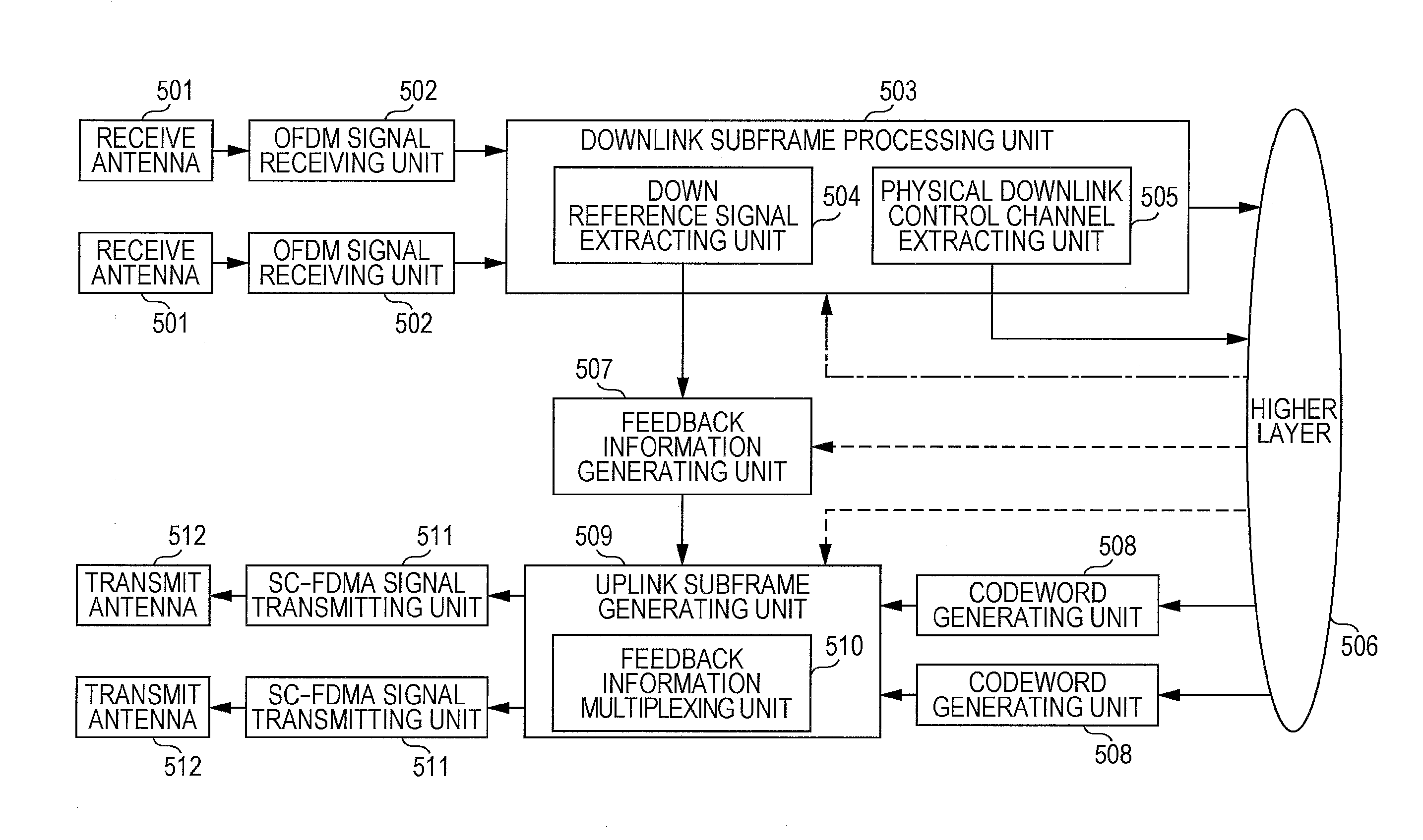
[0085]In the first embodiment, the configuration in that the CSI corresponding to the second and subsequent CSI-RSs is calculated in both subframe sets in a case where the subframe sets are configured, has been described. In contrast, in a second embodiment, a configuration in that the CSI corresponding to the second and subsequent CSI-RSs is calculated in the first subframe set in a case where the subframe sets are configured, will be described. Hereinafter, the second embodiment of the present invention will be described with reference to FIGS. 11 to 13. In addition, the base station apparatus and the terminal apparatus according to the embodiment can be realized with the same configuration as the configuration examples shown in FIG. 4 and FIG. 5, and thus the detailed descriptions thereof are not repeated.
[0086]FIG. 11 shows an example of a procedure of the periodic CSI feedback according to the embodiment. The procedure shown in FIG. 11 is an example of a procedure of periodic f...
third embodiment
[0105]In a third embodiment, a configuration of calculating the CSI corresponding to the second and subsequent CSI-RSs in a coordinated multiple point (CoMP) system will be described. Hereinafter, the third embodiment of the present invention will be described with reference to FIGS. 14 to 17. In addition, the base station apparatus and the terminal apparatus according to the embodiment can be realized with the same configuration as the configuration examples shown in FIG. 4 and FIG. 5, and thus the detailed descriptions thereof are not repeated.
[0106]FIG. 14 is a schematic configuration diagram showing a configuration of a communication system according to the third embodiment of the present invention. The communication system of the drawing is assumed to be an LTE-A system, and includes a base station apparatus 1401 which configures cells, a cooperation base station apparatus (or cooperation transmission point) 1402, and a terminal apparatus 1403. In a case of adaptively controlli...
PUM
 Abstract
Description
Claims
Application Information