Forced air warmer

a technology of forced air and warmer, which is applied in the field of forced air warmer, can solve the problems of variable errors incurred in the temperature measurement made by the temperature sensor, one or more vortices to be generated, and difficult calibration, etc., to achieve the effect of improving the reliability of temperature measuremen

Active Publication Date: 2014-02-13
THE SURGICAL INT
View PDF2 Cites 6 Cited by
  • Summary
  • Abstract
  • Description
  • Claims
  • Application Information

AI Technical Summary

Benefits of technology

[0006]A first aspect of the invention provides a forced air warmer comprising: a chamber having an outlet port; an air heater arranged to heat air within the chamber; an air propagator arranged to propagate heated air from the chamber along a heated air flow path passing through the port; and a temperature sensor provided in the heated air flow path to measure the temperature of heated air propagated along the heated air flow path, characterised by an air flow conditioner in the heated air flow path downstream of the temperature sensor, the air flow conditioner being arranged to condition air flow at the temperature sensor so as to improve the reliability of temperature measurements made by the temperature sensor.
[0007]Positioning a temperature sensor in the heated air flow path destabilises the flow of heated air through the port downstream of the temperature sensor. This unstable air flow can cause one or more vortices to be generated. The number, magnitude and orientation of these vortices are dependent on the velocity of the air flow at the temperature sensor and on backstream conditions at the temperature sensor. Because the vortices are variable in number, magnitude and orientation, varying amounts of air are circulated back upstream onto the temperature sensor by the vortices. This causes variable errors to be incurred in the temperature measurements made by the temperature sensor which can be difficult (if not impossible) to account for by calibration. By conditioning the air flow downstream of the temperature sensor, the air flow at the temperature sensor can be stabilised, thus improving the reliability of the temperature measurements made by the temperature sensor (relative to the situation when the air flow conditioner is removed).

Problems solved by technology

This unstable air flow can cause one or more vortices to be generated.
This causes variable errors to be incurred in the temperature measurements made by the temperature sensor which can be difficult (if not impossible) to account for by calibration.
Accordingly, in the absence of the flow conditioner, the errors are incurred in the temperature measurements made by the temperature sensor are variable with changes in the bending profile of the flexible hose.

Method used


Image

  • Forced air warmer
  • Forced air warmer
  • Forced air warmer

Examples


Embodiment Construction

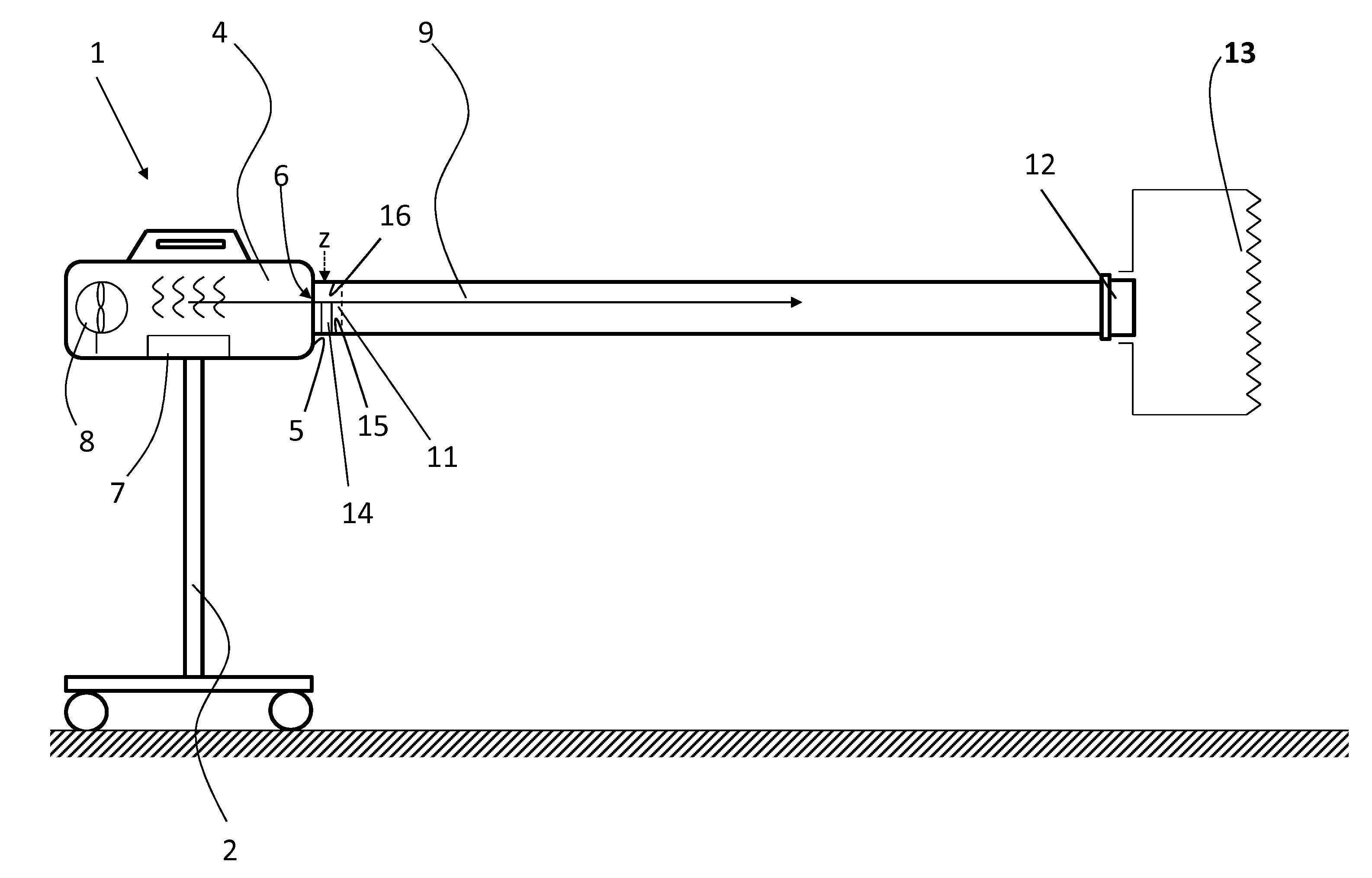
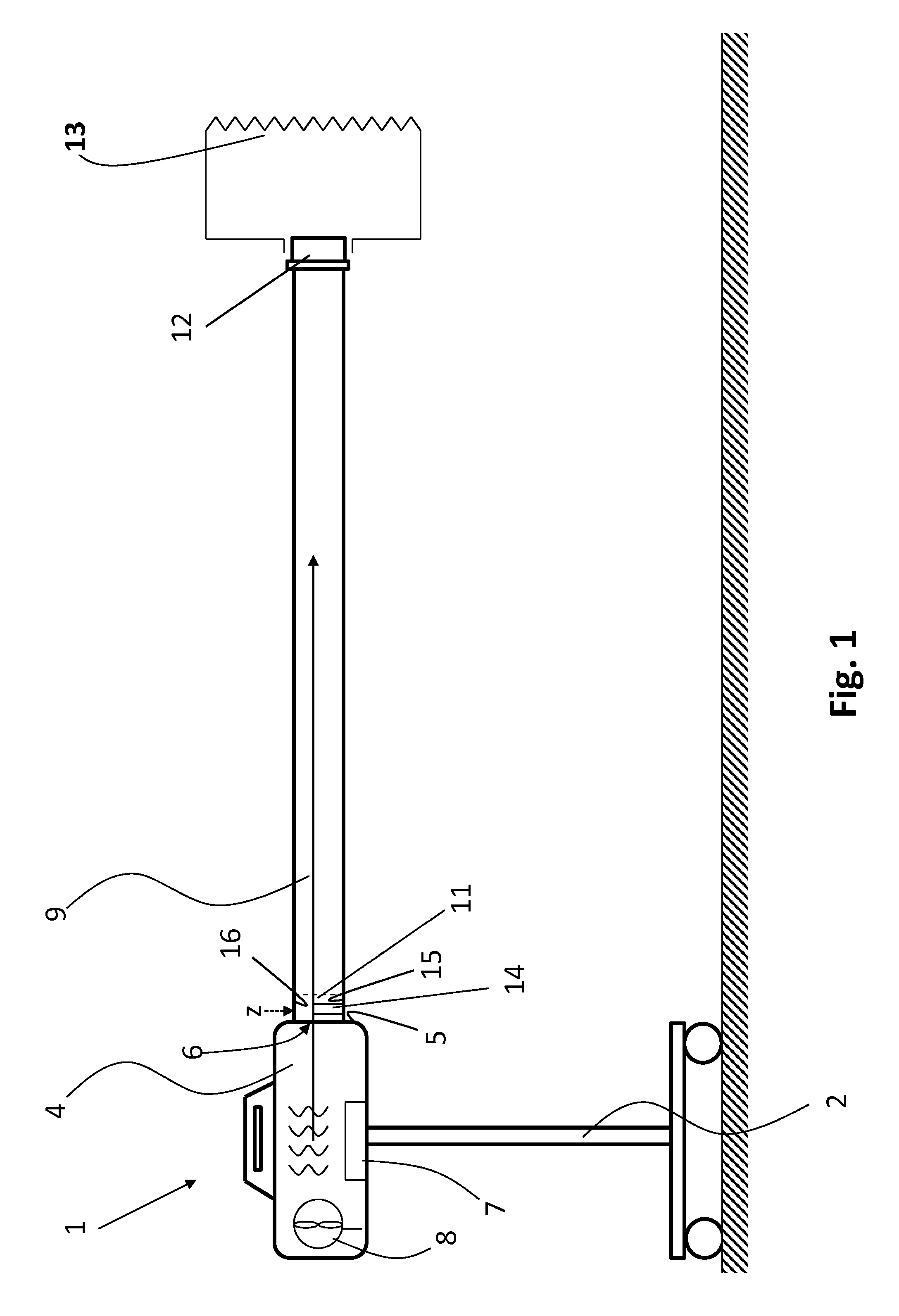
[0093]FIG. 1 is a schematic diagram of a forced air warmer 1 mounted on a trolley 2, the forced air warmer 1 comprising: a chamber 4 having a side wall 5 with an outlet port 6 through which air can exit the chamber 4; an air heater 7 and an air blower 8 housed within the chamber 4; and a flexible hose 9 demountably coupled to the outlet port 6 such that the hose 9 is in fluid communication with the chamber 4.

[0094]The air heater 7 is arranged to heat air within the chamber 4 and the air blower 8 is arranged to propagate heated air from the chamber 4 along a heated air flow path (indicated by an arrow in FIG. 1) passing through the outlet port 6 into the flexible hose 9. The flexible hose 9 comprises a proximal end 11 which is demountably coupled to a cylindrical connector 10 of the outlet port 6 which projects outwardly from the side wall 5 of the chamber 4 and surrounds an opening of the outlet port 6 (shown most clearly in FIG. 12). The flexible hose 9 further comprises a distal e...


PUM


Abstract

The invention provides a forced air warmer comprising: a chamber having an outlet port; an air heater arranged to heat air within the chamber; an air propagator arranged to propagate heated air from the chamber along a heated air flow path passing through the port; and a temperature sensor provided in the heated air flow path to measure the temperature of heated air propagated along the heated air flow path. The forced air warmer further comprises an air flow conditioner in the heated air flow path downstream of the temperature sensor, the air flow conditioner being arranged to condition air flow at the temperature sensor so as to improve the reliability of temperature measurements made by the temperature sensor. The forced air warmer may be used to supply heated air to an air warming blanket for regulating the temperature of a patient.

Description

FIELD OF THE INVENTION[0001]The invention relates to a forced air warmer, a method of measuring the temperature of heated air in a forced air warmer and an air flow conditioner for use in a forced air warmer.BACKGROUND TO THE INVENTION[0002]Forced air warmers may be used in both hypo- and hyperthermia treatments to help to regulate the temperature of a patient. These devices typically comprise an air heating device provided inside a chamber, a flexible hose in air communication with the chamber and a blower arranged to transport heated air from the chamber through the hose into a forced air warming blanket. Typically, the forced air warming blanket comprises an air permeable surface facing the patient.[0003]A key requirement for forced air warmers is that the temperature of the air being provided to the forced air warming blanket can be measured reliably and accurately. The temperature of the heated air would ideally be measured at the forced air warming blanket. However, this is no...

Claims


Application Information

Patent Timeline
Patent Type & Authority Applications(United States)
IPC IPC(8): A61F7/08
CPCA61F7/0085A61F7/007A61F7/0097A61F2007/006A61F2007/0072A61F2007/0086A61F2007/0096
Inventor OFFICIER, ARTHUR EVERARDUS
Owner THE SURGICAL INT
Why Eureka
Try Eureka