Dryer Conveyor Speed Control Apparatus and Method

a control apparatus and conveyor technology, applied in drying machines, lighting and heating apparatus, drying machines with progressive movements, etc., can solve the problems of increasing waste, production costs, and liquification

Inactive Publication Date: 2014-02-20
M&R PRINTING EQUIP
View PDF27 Cites 22 Cited by
  • Summary
  • Abstract
  • Description
  • Claims
  • Application Information

AI Technical Summary

Problems solved by technology

In the ranges below 320 degrees and above 350 degrees, the plastisol will not properly set, resulting in cracking, or it may become liquified.
Moreover, if a dye in the textile is overheated, it will migrate, or the textile or substrate may scorch or burn, increasing waste and production costs.

Method used


Image

  • Dryer Conveyor Speed Control Apparatus and Method
  • Dryer Conveyor Speed Control Apparatus and Method
  • Dryer Conveyor Speed Control Apparatus and Method

Examples


Embodiment Construction

[0017]While this invention is susceptible of embodiments in many different forms, there is shown in the drawings and will herein be described in detail preferred embodiments of the invention with the understanding that the present disclosure is to be considered as an exemplification of the principles of the invention and is not intended to limit the broad aspect of the invention to the embodiments illustrated.

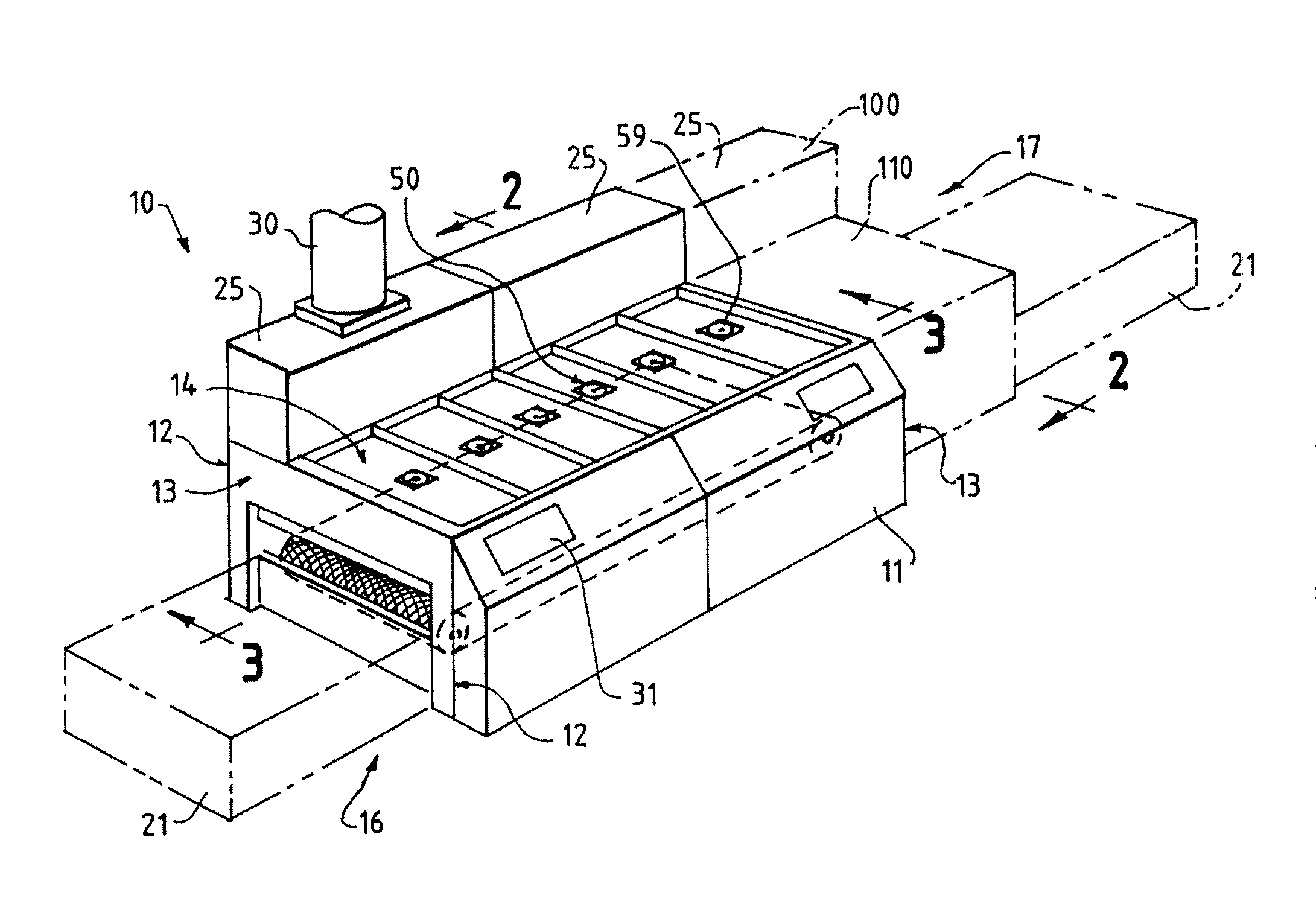
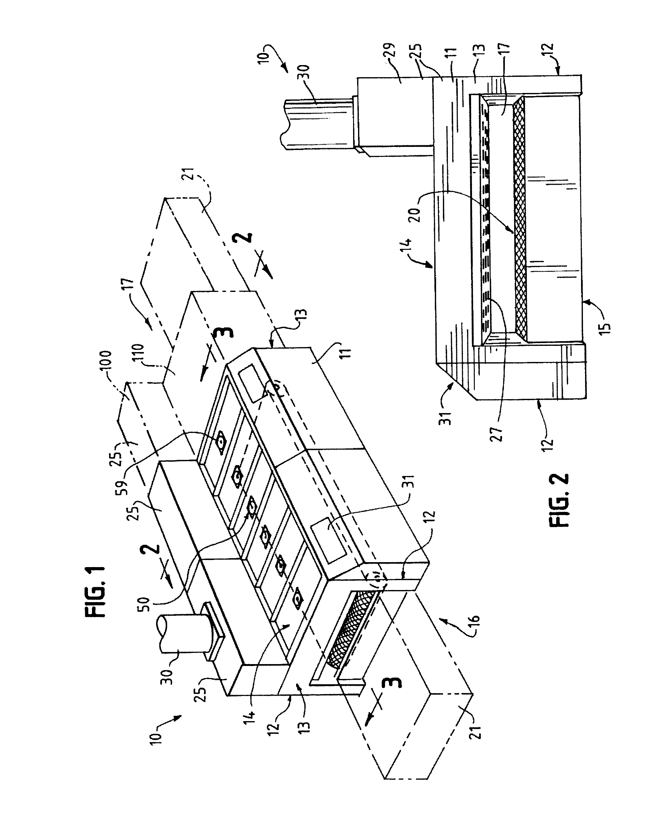
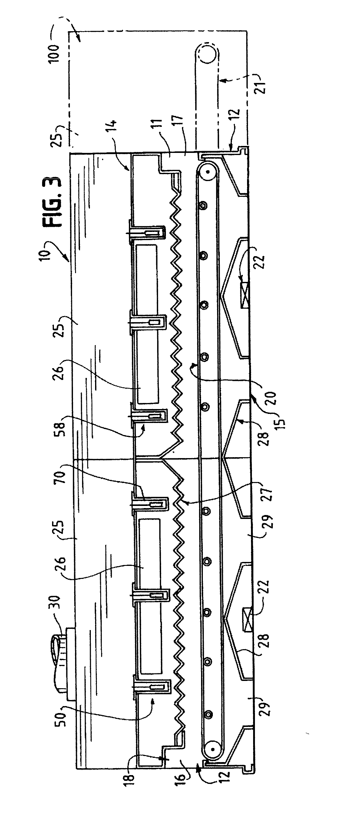
[0018]Referring to the Figures, FIG. 1 shows a dryer 10 of an embodiment of the present invention. The dryer 10 is of a type generally described in U.S. Pat. No. 5,937,535, incorporated herein by reference, and from which FIG. 1 is reproduced. The dryer 10 includes a dryer housing 11 wherein the products passing therethrough are heated. The housing 11 is formed of opposed side walls 12, opposed end walls 13, a top wall 14 and a bottom wall 15. Such walls are generally constructed of sheet metal and with a double wall to keep the outer wall cool. At one end of the housing there ...


PUM


Abstract

In one embodiment, a conveyor speed control system for a dryer is provided. The system includes a dryer having a housing with an entrance and an exit, and a conveyor within the housing, the conveyor capable of moving at a desired speed. A sensor senses the temperature of the interior of the dryer housing. A controller is provided. The controller receives a signal from the temperature sensor. The controller also controls the speed of the conveyor, and limits the speed of the conveyor to a desired speed until a desired dryer housing temperature is attained.

Description

CROSS-REFERENCE TO RELATED APPLICATIONS[0001]The present application claims the benefit of U.S. Provisional Patent Application Ser. No. 61 / 684,244, filed Aug. 17, 2012, the contents of which are incorporated herein by reference.FEDERALLY SPONSORED RESEARCH OR DEVELOPMENT[0002]N / ATECHNICAL FIELD[0003]The present invention generally relates to an apparatus and method for controlling the conveyor speed of a textile dryer upon startup to conserve energy.BACKGROUND OF THE INVENTION[0004]Indicia applied to articles of clothing and other textiles have become very popular. Fanciful indicia, such as slogans, logos, college names, sports team names and logos, and sayings are commonplace.[0005]Indicia are printed using screen printing machines, with one or more colors. Typically, a screen printing machine has at least one station to print each color. Each station generally includes a printing head, which supports a single screen, the ink, and a mechanism for applying the ink to the textile or ...

Claims


Application Information

Patent Timeline
Patent Type & Authority Applications(United States)
IPC IPC(8): F26B25/00
CPCF26B25/001F26B15/18F26B21/10F26B25/00
Inventor QUIRK, BRIANMAUBAN, BERNABE
Owner M&R PRINTING EQUIP
Why Eureka
Try Eureka