Eye gaze user interface and calibration method

a user interface and eye tracking technology, applied in the field of eye tracking device user interfaces, can solve the problems of obstructing the conversation, inadvisable or socially awkward to break off the conversation, insulting important clients or loved ones, etc., and achieve the effect of minimal user training

Active Publication Date: 2014-02-20
SNAP INC
View PDF23 Cites 82 Cited by
  • Summary
  • Abstract
  • Description
  • Claims
  • Application Information

AI Technical Summary

Benefits of technology

[0006]In one embodiment, the invention may be a software controlled user interface and method for an eye gaze controlled device, designed to accommodate angular accuracy versus time averaging tradeoffs for eye gaze direction sensors. The method is simple, intuitive, and can scale between displaying a small to large number of different eye gaze target symbols at any given time, yet still transmit a large array of different symbols to outside devices with minimal user training At least part o

Problems solved by technology

Thus in both business and in private matters, when an individual is not able to instantly respond to at least text messages, this expectation goes unmet, and social friction and/or lost business opportunities can result.
However the act of turning on a cell phone, scrolling through incoming text messages, and then responding to the text messages can be obtrusive, conspicuous and in some situations inappropriate.
Thus there are many times when it is inadvisable or socially awkward to break off a conversation to respond to an incomi

Method used


Image

  • Eye gaze user interface and calibration method
  • Eye gaze user interface and calibration method
  • Eye gaze user interface and calibration method

Examples


Embodiment Construction

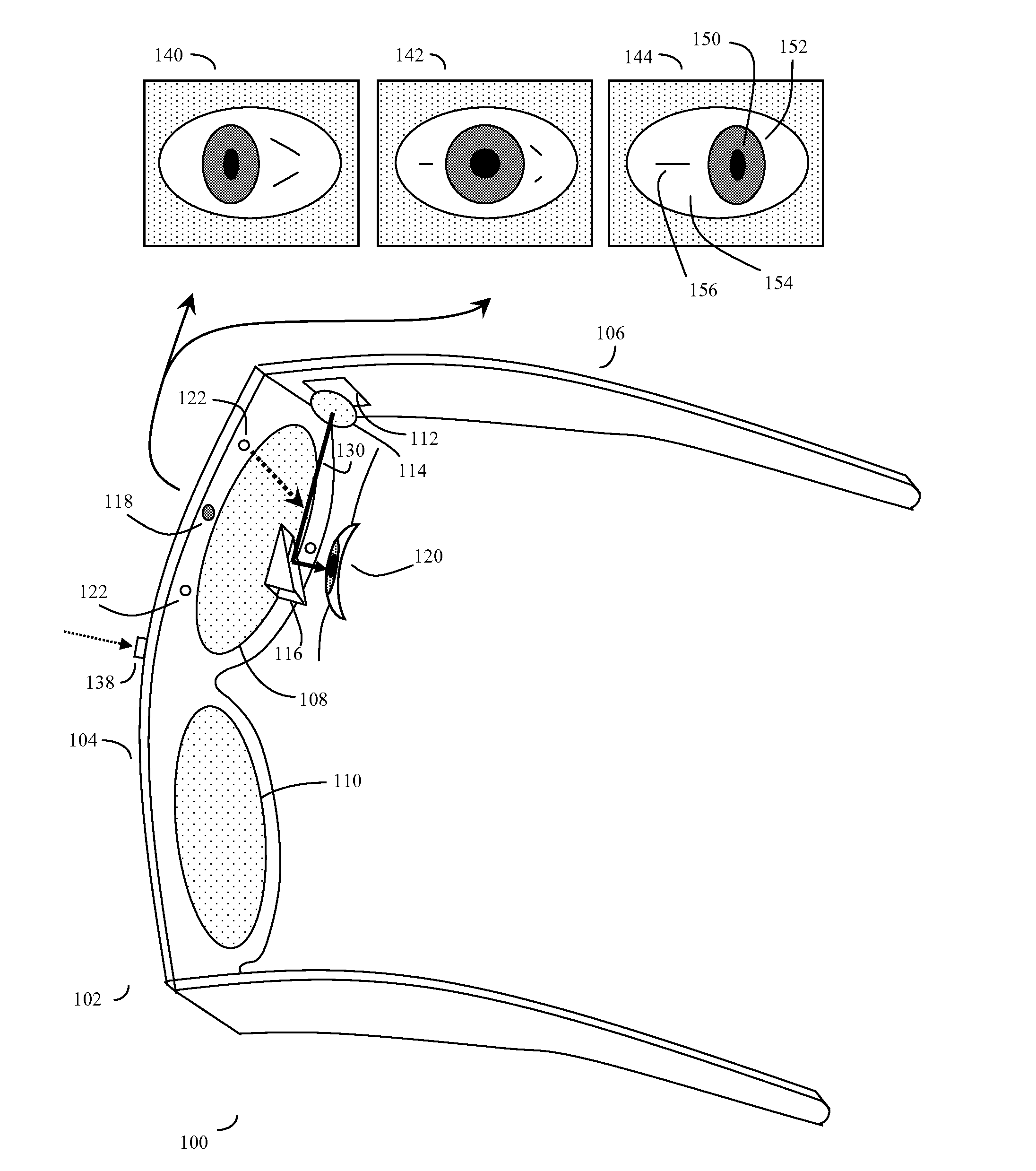
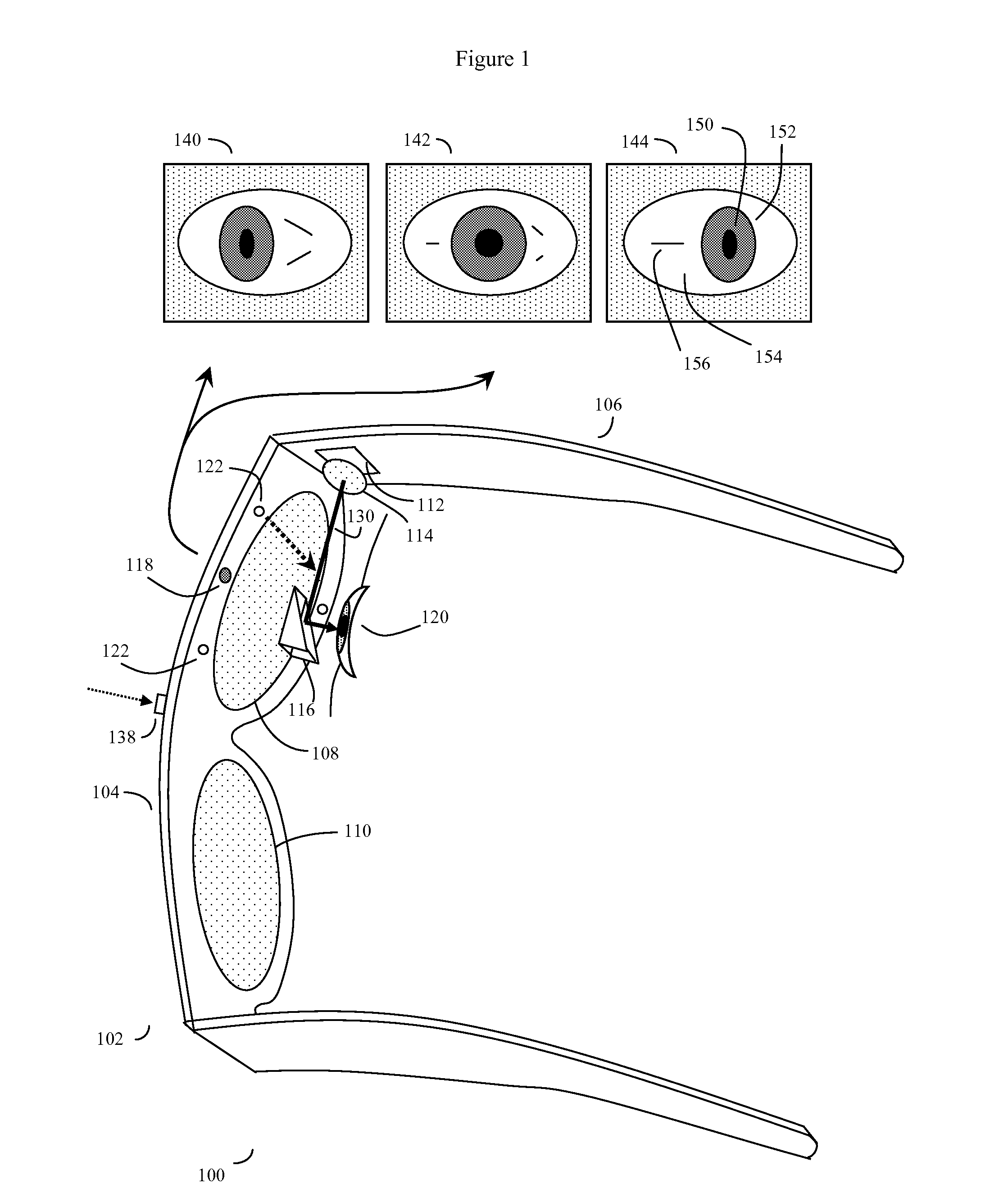
[0020]Although various eye gaze controlled devices have been proposed, exemplified by copending patent application Ser. No. 12 / 842,315, the contents of which are incorporated herein by reference, in addition to the rather complex problem of providing the eye gaze controlled device itself, a second major problem is to devise a simple to use but flexible user interface to control these devices. Here the problems in designing such a user interface should be appreciated. The human eye, which acts as a bit of a cross between a camera and a scanner, is in near constant motion. Instead of gazing at an object of interest in a fixed manner like a camera, the eye also moves to scan the object of interest and the surrounding area as a series of rapid eye motion saccades. Thus in order to determine exactly what an eye is really looking at, the eye position sensors must generally track the eye's direction of gaze for a sufficient period of time to compute a reasonably accurate average gaze posit...


PUM


Abstract

A software controlled user interface and calibration method for an eye gaze controlled device, designed to accommodate angular accuracy versus time averaging tradeoffs for eye gaze direction sensors. The method can scale between displaying a small to large number of different eye gaze target symbols at any given time, yet still transmit a large array of different symbols to outside devices with minimal user training. At least part of the method may be implemented by way of a virtual window onto the surface of a virtual cylinder, with eye gaze sensitive symbols that can be rotated by eye gaze thus bringing various groups of symbols into view, and then selected by continual gazing. Specific examples of use of this interface and method on an eyeglasses-like head-mountable, vision-controlled, device are disclosed, along with various operation examples including sending and receiving text messages, control of robotic devices and control of remote vehicles.

Description

BACKGROUND OF THE INVENTION[0001]This application is a continuation in part of U.S. patent application Ser. No. 13 / 117,146 entitled “EYE GAZE USER INTERFACE AND METHOD”, inventor Gregory A Maltz, filed May 27, 2011; application Ser. No. 13 / 117,146 in turn was a continuation in part of U.S. patent application Ser. No. 12 / 842,315, “Unitized, Vision-Controlled, Wireless Eyeglass Transceiver”, filed Jul. 23, 2010, Inventor Gregory A Maltz, now U.S. Pat. No. 8,531,3558; Ser. No. 13 / 117,146 was also a continuation in part of U.S. patent application Ser. No. 13 / 034,182, “Unitized, Vision-Controlled, Wireless Eyeglasses Transceiver”, filed Feb. 24, 2011, Inventor Gregory A. Maltz, now U.S. Pat. No. 8,531,394; the contents of all these disclosures are incorporated herein by reference.FIELD OF THE INVENTION[0002]The invention is in the field of user interfaces for eye tracking devices, particularly as applied to the control of wireless communication and other devices.DESCRIPTION OF THE RELATE...

Claims


Application Information

Patent Timeline
IPC IPC(8): G06F3/01G02B27/01
CPCG02B27/017G06F3/013G02B2027/0138G02B2027/014G02B2027/0178G02B2027/0187G06F3/04842
Inventor MALTZ, GREGORY A.
Owner SNAP INC
Why Eureka
Try Eureka