Eureka AIR delivers breakthrough ideas for toughest innovation challenges, trusted by R&D personnel around the world.

Unitized eye-tracking wireless eyeglasses system

a wireless eyeglass and wireless technology, applied in the field of eye-tracking wireless eyeglasses system, can solve the problems of augmented data becoming less useful, augmented image that the device user cannot then quickly and easily select for an additional computing, such as sharing with contacts, and less useful than augmented image that also affords additional actionable options, cell phone or other handheld mobile device, to achieve the effect of minimal user training

Active Publication Date: 2020-01-07
SNAP INC
View PDF11 Cites 2 Cited by
  • Summary
  • Abstract
  • Description
  • Claims
  • Application Information

AI Technical Summary

Benefits of technology

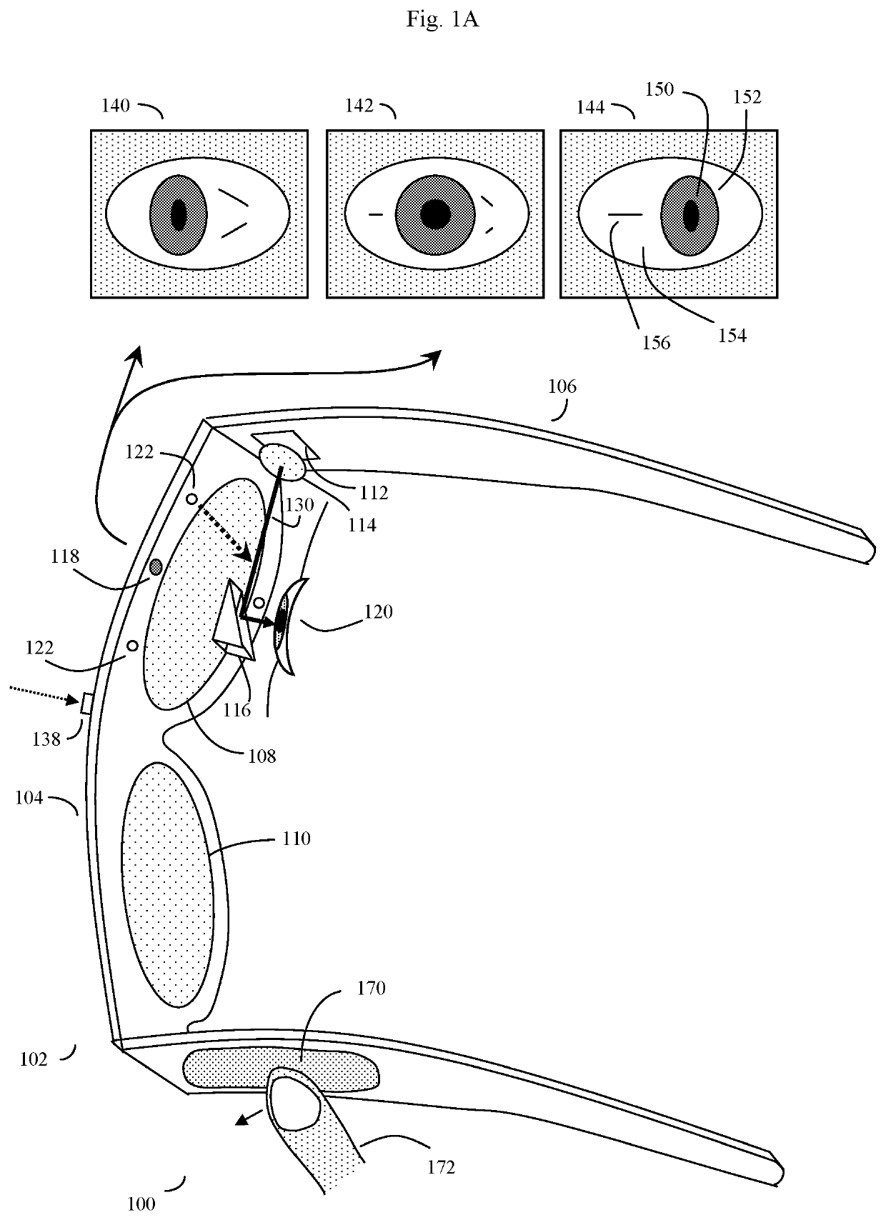
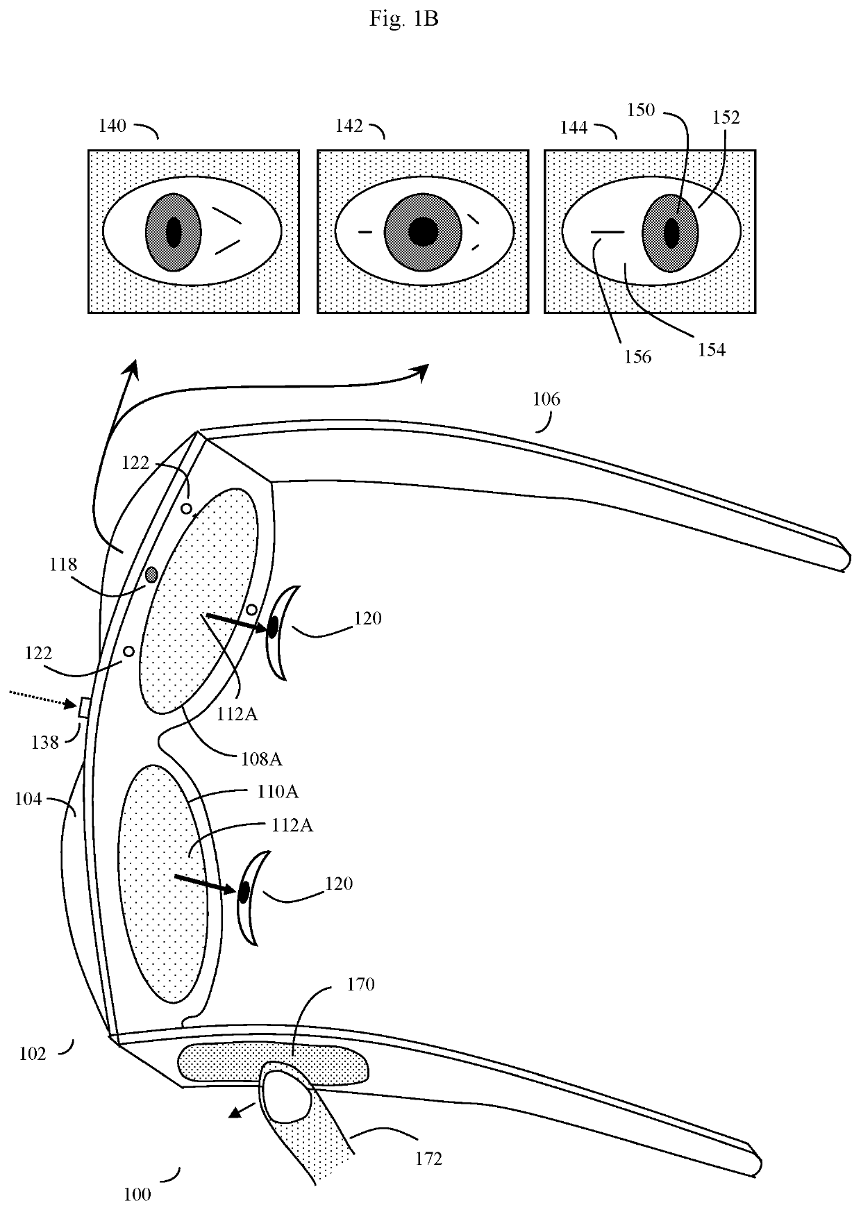
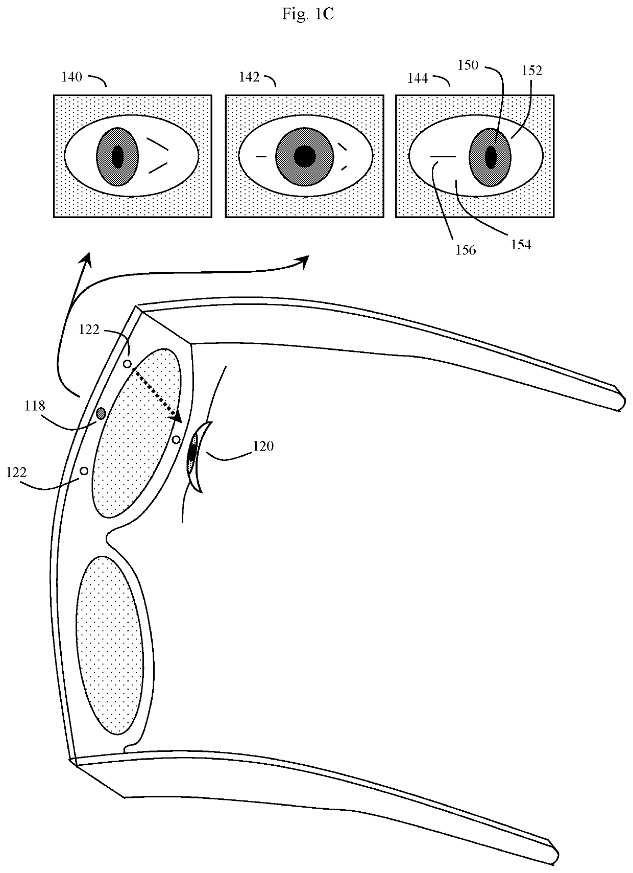
[0011]An additional improvement over prior art devices, such as the eye tracking devices of Lemelson, is that the present invention can operate without the need of a visible cursor, and indeed without any built-in display at all. As will be discussed, the invention discloses user interfaces that operate so that at least some of the motion and eye gaze direction of the user's eye (or eyes) can be done without tracking the position of a moveable cursor. Thus, the transmitted wireless information can be transmitted without requiring the use of a moveable cursor.
[0013]The method is simple, intuitive, and when used in conjunction with a visual display can scale between displaying a small to a large number of different target symbols at any given time, yet still transmit a large array of different symbols to outside devices with minimal user training. In some embodiments, at least part of the method may be implemented by way of a virtual window onto the surface of a virtual cylinder, with sensitive symbols that can be rotated either by changes in eye gaze direction, e.g., pupil position, or alternatively by fingertip swiping to bring various groups of symbols into view, and then selected. Specific examples of the use of this interface and method on an eyeglasses-like head-mountable, device are disclosed, along with various operation examples including sending and receiving text messages and control of the head-mountable device, as well as other external devices. In the context of real, virtual or augmented data being presented to the user, the invention may allow the user to interact with the data in many ways.
[0014]The method will generally use either at least one eye position sensor or touch sensor (such as a touchpad—i.e. a touch-tracking touchpad sensor or other type of touch sensor, which may be built into the device or alternatively tethered physically or wirelessly to the device) to determine how the user is interacting with a plurality of visible elements displayed by an optional eyewear device screen or another type of display. In some embodiments, a virtual touchpad projected by the eyewear device may also be used instead of a hardware touchpad. The method will keep track of either the user's eye gaze direction, or the user's finger movement, and make visual changes in the display. Alternatively, the invention may signal the user by other sensory means such as mild vibration, sound, or other alternative method.
[0017]In a typical embodiment, only some of these visible elements will generally be presented or displayed at any one time to the user via an optional virtual display. However, by either gazing or using fingertip commands to rotate the virtual solid, or to move to different rows of symbols on the surface of this virtual solid, the sequence of displayed visible elements can be scrolled through in a predictable manner. When touch control is desired, touches on the touchpad can be registered as a keystroke by the system, and thus used for various functions as described above. Likewise, swiping the finger up, down, or side to side can rotate the virtual solid to rapidly scroll through the virtual keys, symbols, or data to access the desired content.

Problems solved by technology

If this functionality is not addressed by the user interface, the augmented data becomes less useful, and social friction and / or lost business opportunities can result.
For example, an augmented image that the device user cannot then quickly and easily select for an additional computing, such as sharing with contacts, is less useful than one that also affords additional actionable options.
However, the act of using a cell phone or other handheld mobile device to perform a computing command in response to any real, virtual, or augmented data can be obtrusive, conspicuous and in some situations inappropriate.
Thus there are many times when it is inadvisable or socially awkward to operate applications or respond to incoming data or images.
Thus at present, a mobile user is faced with the difficult problem of trying to balance priority between the environment e.g., the person, data or object they are addressing in the physical world, versus the person, data or object that is presented virtually or augmented by the mobile device.

Method used


Image

  • Unitized eye-tracking wireless eyeglasses system
  • Unitized eye-tracking wireless eyeglasses system
  • Unitized eye-tracking wireless eyeglasses system

Examples


example 1

[0147]The camera and computer vision recognition system pick up an image of a check or other financial instrument. The computer vision system transmits a prompt to the device that the device should pull up the user interface virtual solid, here customized with targets for various financial transactions (e.g. depositing into the user's bank account, and the like).

example 2

[0148]The camera and computer vision recognition system pick up a retail store in the vicinity of the user, and that retail store may offer for sale a pair of shoes that the user may be interested in purchasing. For example, the shoes may appear as an augmented reality image to the user based on the user's interaction with a particular shoe type online, at home or at a different store (e.g. different GPS location or online) within a recent time window (say perhaps the last week). The user or the augmented reality application may have trained the device to scan for that type of product, whereupon the computer vision system recognizes the product of interest in the inventory of a nearby store, the system can transmit a prompt to the device that displays an appropriate image of the products with relevant data, e.g., sale price, and again can pull up the appropriate user interface targets in such a manner that the user can quickly select to access useful information such as comparative ...

example 3

[0150]The user may be in a situation where he or she has to cope with an unwieldy number of items, such as packages or crates for shipment or storage. Here the head mounted device may be configured to use its camera (138) to automatically recognize barcodes on the surface of these various items. The head-mounted device can also be configured to automatically bring up an augmented reality image of the appropriate place to move the package for proper shipping or storage. The head-mounted device may also display a rotating solid (virtual carousel) of with various targets that may represent, for example, package's sender, intended recipient, item identification, item weight, other packages associated with that particular item, and so on.

[0151]The targets, when selected and activated, can yield important information that may facilitate shipping or be transmitted, along with the augmented reality image, to the sender or other interested parties.

[0152]In other embodiments, the device may c...


PUM


Abstract

A user-worn eye-tracking device, method, and system. The eye-tracking device may have an outward appearance resembling standard eyeglasses or sunglasses, and may also comprise a built-in wireless transceiver and an optional optical display. In addition to eye-tracking, the device can allow the user to inconspicuously transmit data by a process in which the user simply moves his or her eyes and / or optionally gazes at various internal or external display targets. The device's eye tracking system and software track the motion and gaze of the user's eyes, and convert this gaze into eye-position data and / or message symbols and system control commands. The device then transmits any of the resulting eye position data, commands or messages using its transceiver. In a preferred embodiment, the device is self-contained and operates, when placed on the user's head, without the need of external battery packs or external transceivers.

Description

[0001]This application is a continuation in part of U.S. patent application Ser. No. 14 / 798,349; application Ser. No. 14,789,348 was a continuation in part of U.S. patent application Ser. No. 14 / 716,510, “EYEWEAR DEVICE USER INTERFACE AND METHOD”, filed May 19, 2015; application Ser. No. 14 / 716,510 in turn is a continuation in part of U.S. patent application Ser. No. 14 / 066,654, “EYE GAZE USER INTERFACE AND CALIBRATION METHOD”, filed Oct. 29, 2013; Ser. No. 14 / 066,654 was a continuation in part of U.S. patent application Ser. No. 13 / 117,146, “EYE GAZE USER INTERFACE AND METHOD” filed May 27, 2011, now U.S. Pat. No. 8,593,375; Ser. No. 13 / 117,146, in turn, was a continuation in part of U.S. patent application Ser. No. 13 / 034,182 filed Feb. 24, 2011, now U.S. Pat. No. 8,531,394; Ser. No. 13 / 117,146 was also a continuation in part of U.S. patent application Ser. No. 12 / 842,315, “Unitized, Vision-Controlled, Wireless Eyeglass Transceiver”, filed Jul. 23, 2010; now U.S. Pat. No. 8,531,35...

Claims


Application Information

Patent Timeline
Patent Type & Authority Patents(United States)
IPC IPC(8): G06F3/01G02B27/01
CPCG02B27/017G06F3/013G02B2027/0178G02B2027/0138G02B2027/0187
Inventor MALTZ, GREGORY A.
Owner SNAP INC
Why Eureka
Eureka Blog
Learn More