Eureka AIR delivers breakthrough ideas for toughest innovation challenges, trusted by R&D personnel around the world.

Deployment system for intraluminal devices

Inactive Publication Date: 2005-05-31
WL GORE & ASSOC INC
View PDF33 Cites 184 Cited by
  • Summary
  • Abstract
  • Description
  • Claims
  • Application Information

AI Technical Summary

Benefits of technology

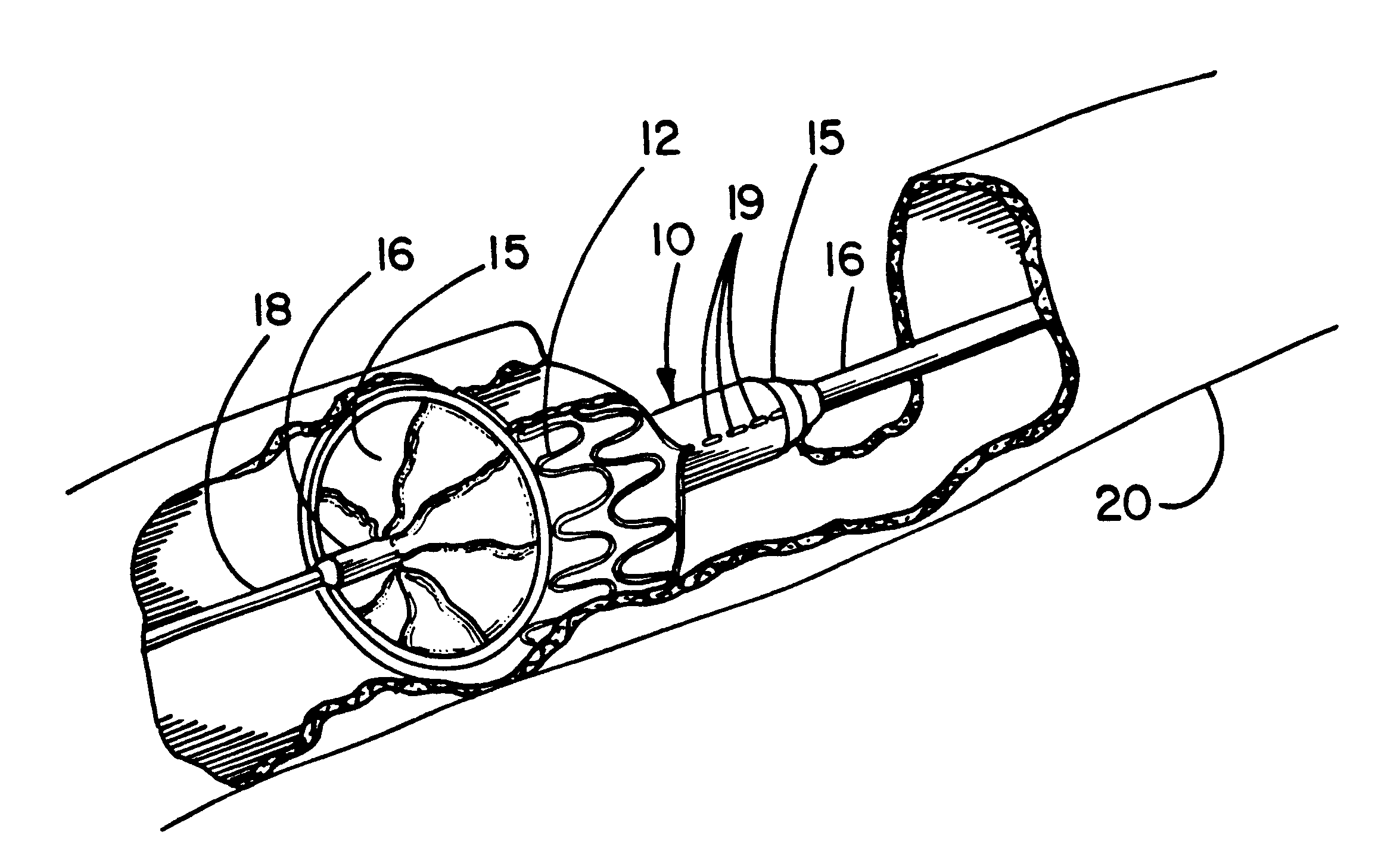
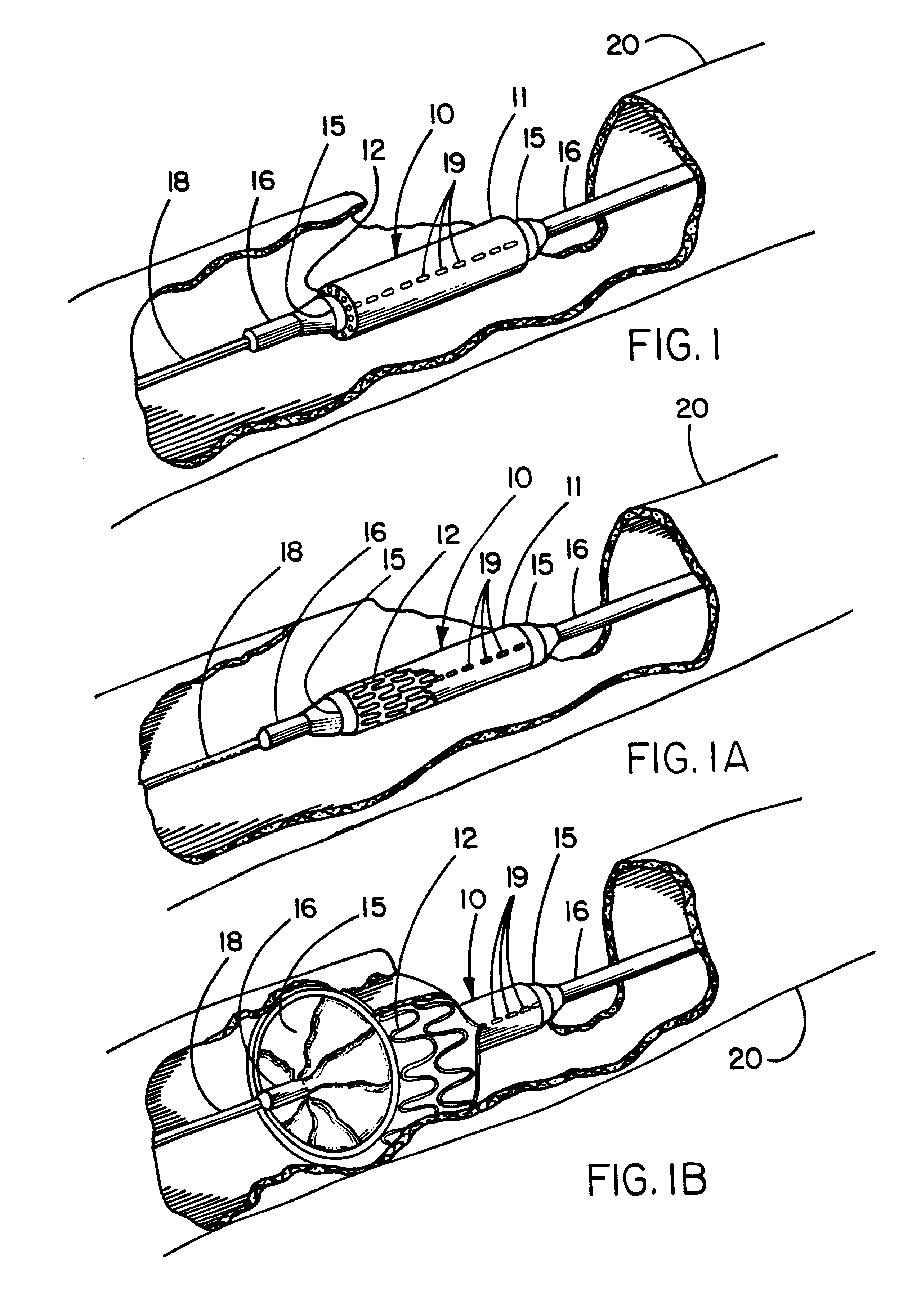
[0016]With regard to either a self-expanding or a balloon expandable endoprosthesis, the constraining sheath may be employed to provide a smoother and more lubricious exterior surface during delivery than would be possible with a balloon expandable stent that would otherwise present a relatively rough exterior surface to the lumen of the blood vessel into which it is inserted.
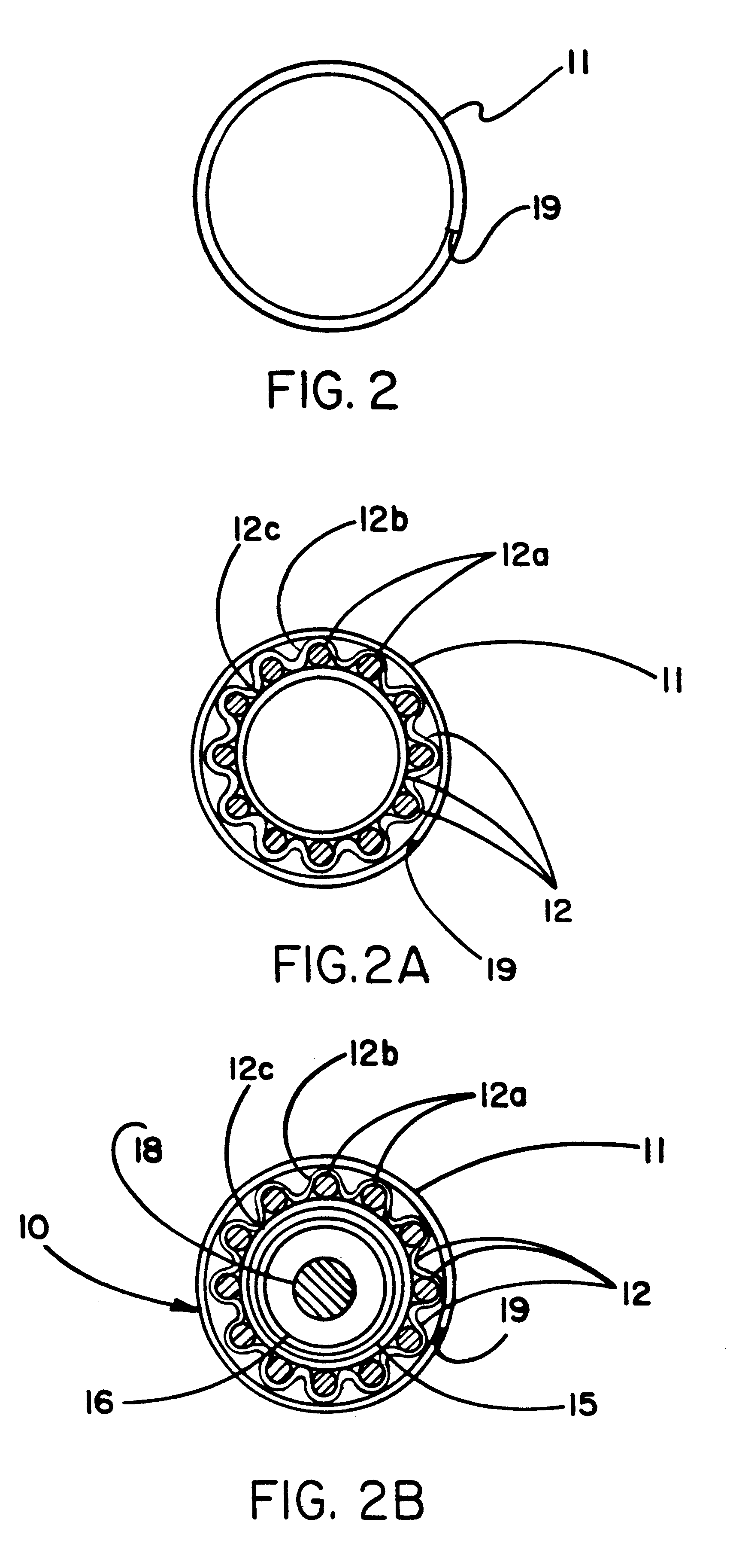
[0017]The break-away constraining sheath of the present invention overcomes many of the disadvantages of the previously described delivery systems and establishes numerous unique advantages. The sheath of the present invention, particularly when made of ePTFE, has a much smoother, continuous outer surface than the fiber based systems, which may reduce the incidence of iatrogenic endothelial traumatization. It may be used to deploy a device beginning at the tip end and progressing to the hub end (i.e., distal end to proximal end), or hub end to tip end, or both ends toward the middle, or middle to both ends. The constraining sheath when made of a preferred ePTFE material may be provided with an extremely thin wall thickness (adding only 0.025-0.050 mm to total introductory profile) while providing extremely high strength. This enables substantial diametrical compaction of the device. The ePTFE sheath can allow almost immediate tissue ingrowth due to its inherent porous microstructure and thereby assist in anchoring the endoprosthesis. The sheath can be affixed to the exterior of an endoprosthesis, or alternatively can be provided without direct attachment to the endoprosthesis.
[0019]The deployment mechanism mimics the procedural techniques used with popular balloon-expandable endoprostheses and thus will require minimal user training. The flexibility of the delivery system is minimally compromised, which is important for device delivery through tortuous anatomy. Reliability of deployment may be improved. There is a high degree of confidence in deployment reliability since this constraint is not compromised by subsequent stitching or the use of pull strings, rip-cords or deployment lines, creep of constraints, overcoming high static frictional forces, etc. Since the sheath is provided over an endoprosthesis mounted on the angioplasty balloon, this system affords the opportunity for “primary stenting,” that is, device implantation without preceding balloon dilatation of the host vessel. If primary stenting proves feasible for the particular patient, fluoroscopy time may be reduced (reducing the exposure of both patient and clinician to x-ray), as well as overall procedural time and expense. Risk of emboli formation may also be reduced. Additionally, once implanted, the self-expanding device is completely unconstrained, thereby allowing for compensatory remodeling (i.e., continued enlargement of the endoprosthesis over time).
[0022]Disruption of the inventive constraining sheath is possible via other methods which typically involve creating a line or zone of weakness along the length of the sheath such as by the use of a lesser amount of material in the zone of weakness. Other methods of creating a zone of weakness may include the application of thermal or mechanical treatments to a localized region. Additionally, active elements such as spring components or elastic segments included with the sheath may be used to facilitate constraining sheath removal.
[0024]The constraining sheath may be imbibed with various pharmaceutical, biological, or genetic therapies for targeted luminal delivery of these substances. Following deployment of the endoprosthesis, these therapeutic agents can be released over time. An advantage of this approach is that the loading of the sheath with any of these therapeutic agents can be performed independent of the endoprosthesis manufacture. Further, radiopaque elements may be incorporated into the constraining sheath to facilitate fluoroscopic visualization.

Problems solved by technology

The endoluminal delivery and deployment of self-expanding endoprostheses pose several unique problems.
Existing problems and / or complications with the tubular coaxial sheath type of delivery system include friction between compacted device and constraining sheath, friction between the constraining sheath and delivery catheter, and friction between the delivery catheter and constraining sheath hemostasis valve, all of which can hinder deployment accuracy, speed and control.
Additionally, a tubular coaxial constraining sheath can also reduce flexibility and add introductory profile due to the thickness of the constraining sheath.
The Duerig et al. device is delivered from a conventional balloon catheter, but thought to have limitations, including radial recoil of the sheath after the balloon is pressurized, which can compromise luminal gain.
Further, the presence of the cover may adversely affect the ability of the stent to fully deploy.
Problems with fiber-based type of delivery systems include possible premature deployment during introduction to the vascular system through hemostasis valves, extra lumens required on the delivery catheter, which can increase profile, possible snagging of fiber(s) on the compacted implantable device, the possibility of emboli resulting from moving lines between the catheter and the blood vessel, and possible breakage of the deployment cord itself.

Method used


Image

  • Deployment system for intraluminal devices
  • Deployment system for intraluminal devices
  • Deployment system for intraluminal devices

Examples


example

[0082]A 0.7 mm inside diameter ePTFE tube of about 20 cm length, about 0.03 mm thick and about 30 micron fibril length is fitted over a stainless steel mandrel of about 1.4 mm diameter. This tube is intended as a sacrificial tube upon which the constraining sheath is subsequently constructed. One end of the ePTFE tube is helically wrapped for a length of about 1 cm with another length of the same ePTFE tubing; this wrap is also sacrificial and intended only to later enable the release of the subsequently applied constraint sheath material. As such, both the underlying ePTFE tube fitted over the mandrel and the helically wrapped material are non-critical choices as long as they are capable of tolerating subsequent heat processing without becoming adhered to the constructed constraint sheath.

[0083]Next, four layers of ePTFE / FEP porous film laminate are applied from a roll of this film over the sacrificial ePTFE tube and helical wrap. The ePTFE film used to manufacture this laminate is...


PUM


Abstract

A constraining sheath for use around an endoprosthesis (e.g., a stent device, with or without a graft covering), which may be a balloon expandable endoprosthesis but more preferably is a self-expanding prosthesis. The endoprosthesis is coaxially enclosed within the constraining sheath, which is an outer, disruptable, preferably implantable tubular sheath, preferably made of ePTFE. The constraining sheath and endoprosthesis are preferably mounted together as an assembly on an angioplasty balloon for delivery. Deployment of the endoprosthesis entails inflating the angioplasty balloon to a pressure sufficient to disrupt or break the constraining sheath in a prescribed fashion, thereby allowing a self-expanding endoprosthesis to spontaneously deploy. The constraining sheath of ePTFE may be attached to the endoprosthesis and implanted along with the device, or alternatively attached to the balloon catheter shaft and removed with the balloon catheter.

Description

FIELD OF THE INVENTION[0001]The present invention relates to the transcatheter delivery and remote deployment of implantable medical devices and more particularly implantable intraluminal devices of either the self-expanding type or the balloon expandable type.BACKGROUND OF THE INVENTION[0002]Endoluminal therapies typically involve the insertion of a delivery catheter that transports an implantable prosthetic device into the vasculature through a small, often percutaneous, access site in a remote vessel. Once access to the vasculature is achieved, the delivery catheter is used to mediate intraluminal delivery and subsequent deployment of the prosthesis via one of several techniques. In this fashion, the prosthesis can be remotely implanted to achieve a therapeutic outcome. In contrast to conventional surgical therapies, endoluminal treatments are distinguished by their “minimally invasive” nature.[0003]Self-expanding endoprostheses are generally comprised of a stent component with o...

Claims


Application Information

Patent Timeline
IPC IPC(8): A61F2/06A61F2/86
CPCA61F2/95A61F2/958A61F2/97A61F2/86A61F2250/0071A61F2002/9511A61F2002/9522A61F2002/9583A61F2/9522
Inventor ARMSTRONG, JOSEPH P.CULLY, EDWARD H.SHAW, EDWARD E.ULM, MARK J.VONESH, MICHAEL J.
Owner WL GORE & ASSOC INC
Why Eureka
Eureka Blog
Learn More