Making display device with pixel-aligned micro-wire electrode

a micro-wire electrode and display device technology, applied in the manufacture of electrode systems, instruments, computing, etc., can solve the problems of limited current-carrying capacity of such electrodes, limited transparency and conductivity, and tendency to crack under mechanical or environmental stress, so as to improve transparency and conductivity, improve transparency, and reduce thickness

Active Publication Date: 2014-02-20
EASTMAN KODAK CO
View PDF2 Cites 23 Cited by
  • Summary
  • Abstract
  • Description
  • Claims
  • Application Information

AI Technical Summary

Benefits of technology

[0021]locating the gap micro-wires of the first micro-pattern between the pixels in the inter-pixel gaps so that the gap micro-wires substantially extend continuously along the first electrode length.
[0022]The present invention provides a display and touch screen device with improved transparency and co

Problems solved by technology

Transparent conductive metal oxides are well known in the display and touch-screen industries and have a number of disadvantages, including limited transparency and conductivity and a tendency to crack under mechanical or environmental stress.
However, the current-carrying capacity of such electrodes is limited, thereby limiting the amount of power that can be supplied to the pixel eleme

Method used


Image

  • Making display device with pixel-aligned micro-wire electrode
  • Making display device with pixel-aligned micro-wire electrode
  • Making display device with pixel-aligned micro-wire electrode

Examples


Embodiment Construction

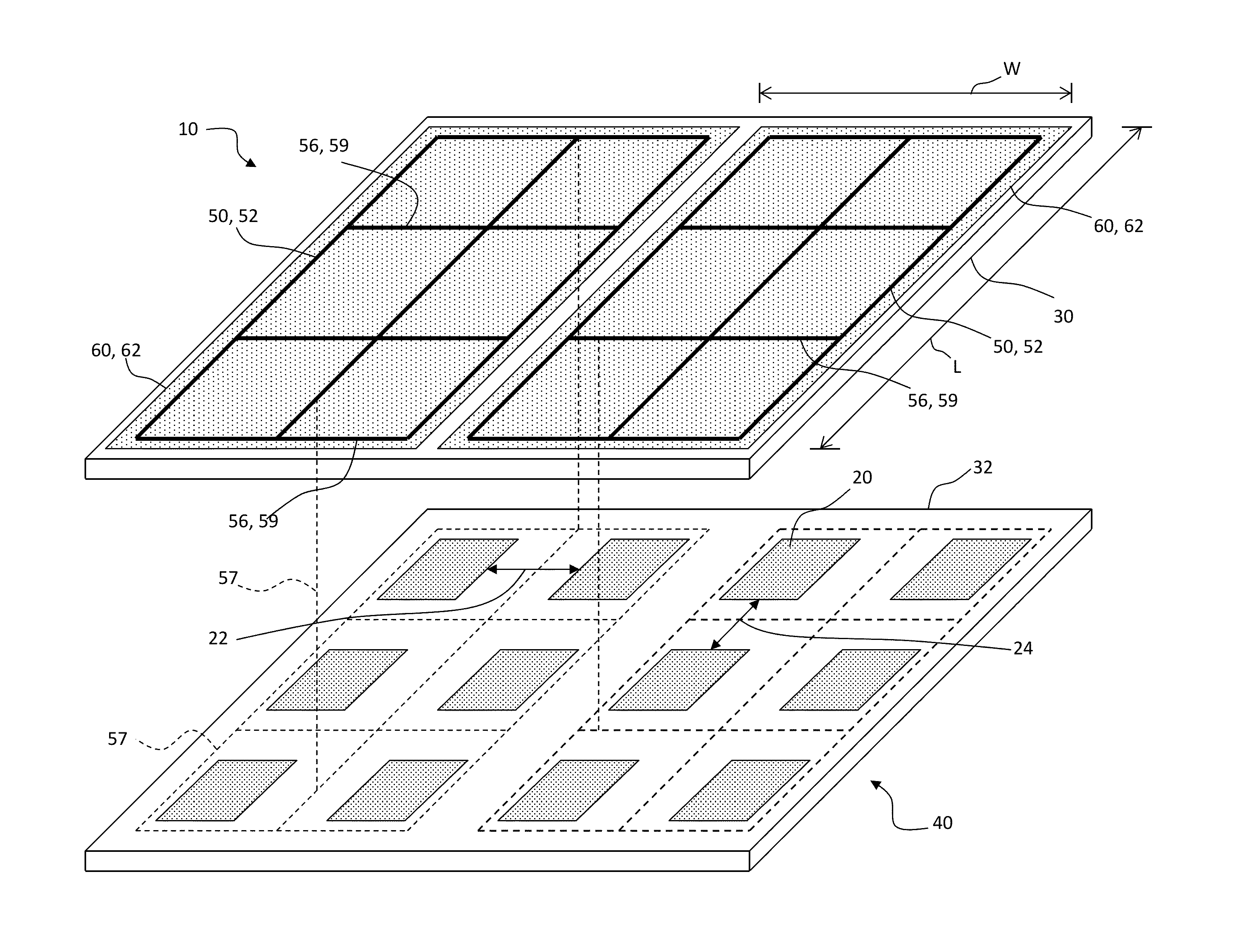
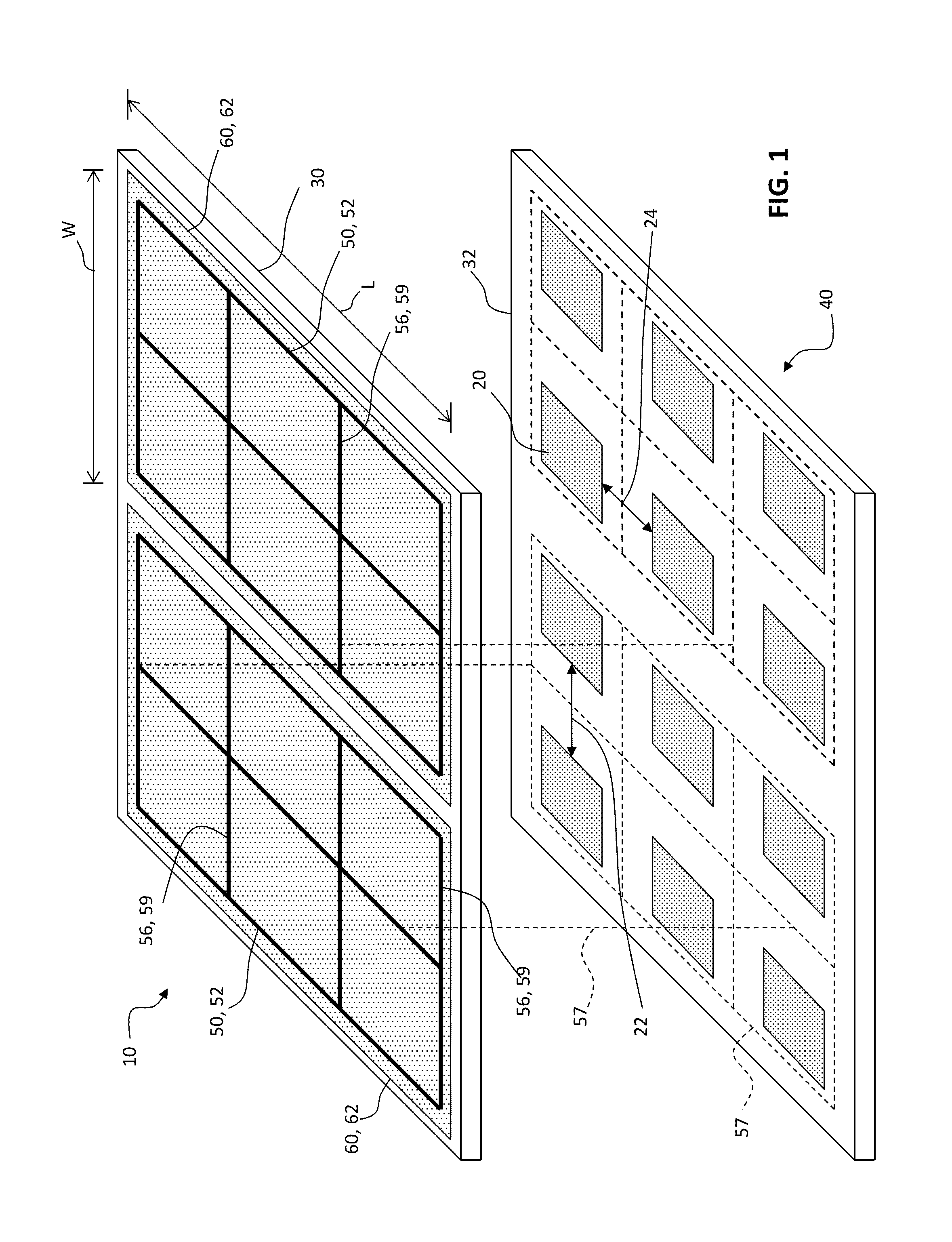
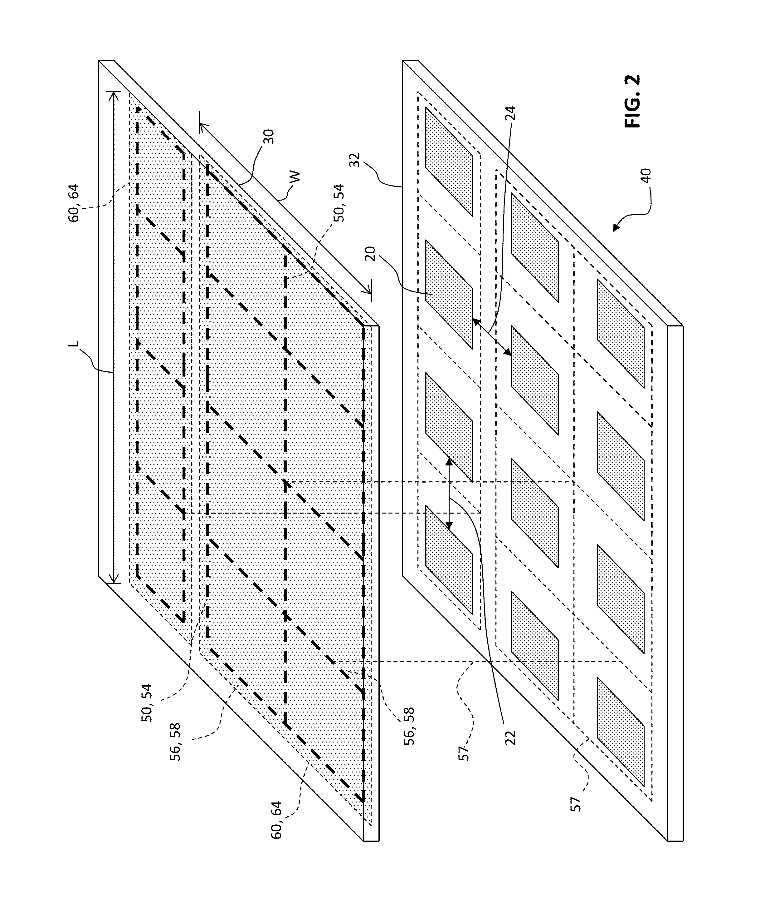
[0037]Referring to FIG. 1 in an embodiment of the present invention, a display device 10 includes a display 40 having an array of pixels 20. The pixels 20 are separated by column inter-pixel gaps 22 between columns of pixels 20 and row inter-pixel gaps 24 between rows of pixels 20. An electrode 60 having a length L and width W is located over display 40 and extends across at least a portion of the array of pixels 20. Electrode 60 includes a plurality of electrically connected micro-wires formed in a micro-pattern. The micro-pattern includes gap micro-wires 50 located between pixels 20 in column inter-pixel gaps 22 or row inter-pixel gaps 24. Gap micro-wires 50 substantially extend continuously along electrode length L.

[0038]The rows and column of pixels 20 illustrated in FIG. 1 are shown in straight lines. However, in other embodiments of the present invention, the rows and columns can be arranged so that pixels 20 in rows or columns can be offset with respect to each other so that ...


PUM


Abstract

A method of making a display device includes providing a first substrate having an array of pixels located in correspondence thereto, the pixels separated by inter-pixel gaps in at least one dimension. A first electrode having a length and width is formed and located over the first substrate and extends across at least a portion of the array of pixels, the first electrode including a plurality of electrically connected micro-wires formed in a first micro-pattern. The method further includes locating the gap micro-wires of the first micro-pattern between the pixels in the inter-pixel gaps so that the gap micro-wires substantially extend continuously along the first electrode length.

Description

CROSS REFERENCE TO RELATED APPLICATIONS[0001]Reference is made to commonly assigned U.S. patent application No. 13 / 571,704 filed Aug. 10, 2012, entitled “Micro-Wire Electrode Pattern” by Ronald S. Cok; U.S. patent application Ser. No. ______ filed concurrently herewith, entitled “Pixel-Aligned Micro-Wire Electrode Device” by Ronald S. Cok; and U.S. patent application Ser. No. ______ filed concurrently herewith, entitled “Display Apparatus With Pixel-Aligned Micro-Wire Electrode” by Ronald S. Cok the disclosures of which are incorporated herein.FIELD OF THE INVENTION[0002]The present invention relates to micro-wire transparent electrodes and their use in a capacitive touch-screen display apparatus.BACKGROUND OF THE INVENTION[0003]Transparent conductors are widely used in the flat-panel display industry to form electrodes that are used to electrically switch light-emitting or light-transmitting properties of a display pixel, for example in liquid crystal or organic light-emitting diod...

Claims


Application Information

Patent Timeline
IPC IPC(8): H01J9/02
CPCG06F3/045G06F2203/04103G06F3/0445G06F3/0446H10K50/814H10K50/824
Inventor COK, RONALD STEVEN
Owner EASTMAN KODAK CO
Why Eureka
Try Eureka