
Mechanical design of deformation compensated flexural pivots structured for linear nanopositioning stages

a technology of deformation compensation and pivots, applied in piezoelectric/electrostrictive/magnetostrictive devices, piezoelectric/electrostriction/magnetostriction machines, electrical instruments, etc., can solve the problems of limited positioning resolution and linear motion straightness of trajectory that is usually not repeatabl

Active Publication Date: 2014-02-27
UCHICAGO ARGONNE LLC
View PDF4 Cites 3 Cited by
  • Summary
  • Abstract
  • Description
  • Claims
  • Application Information

AI Technical Summary

Benefits of technology

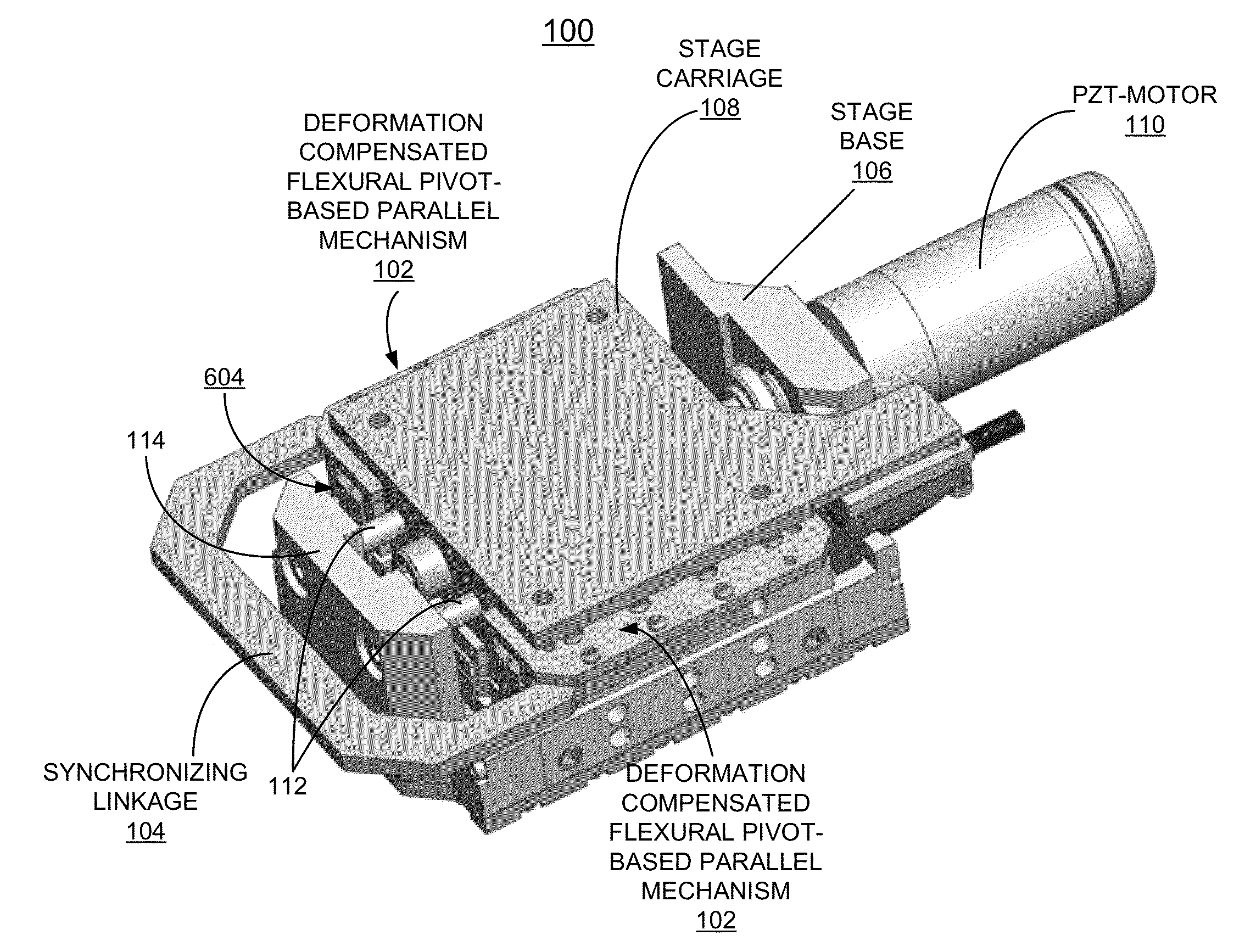
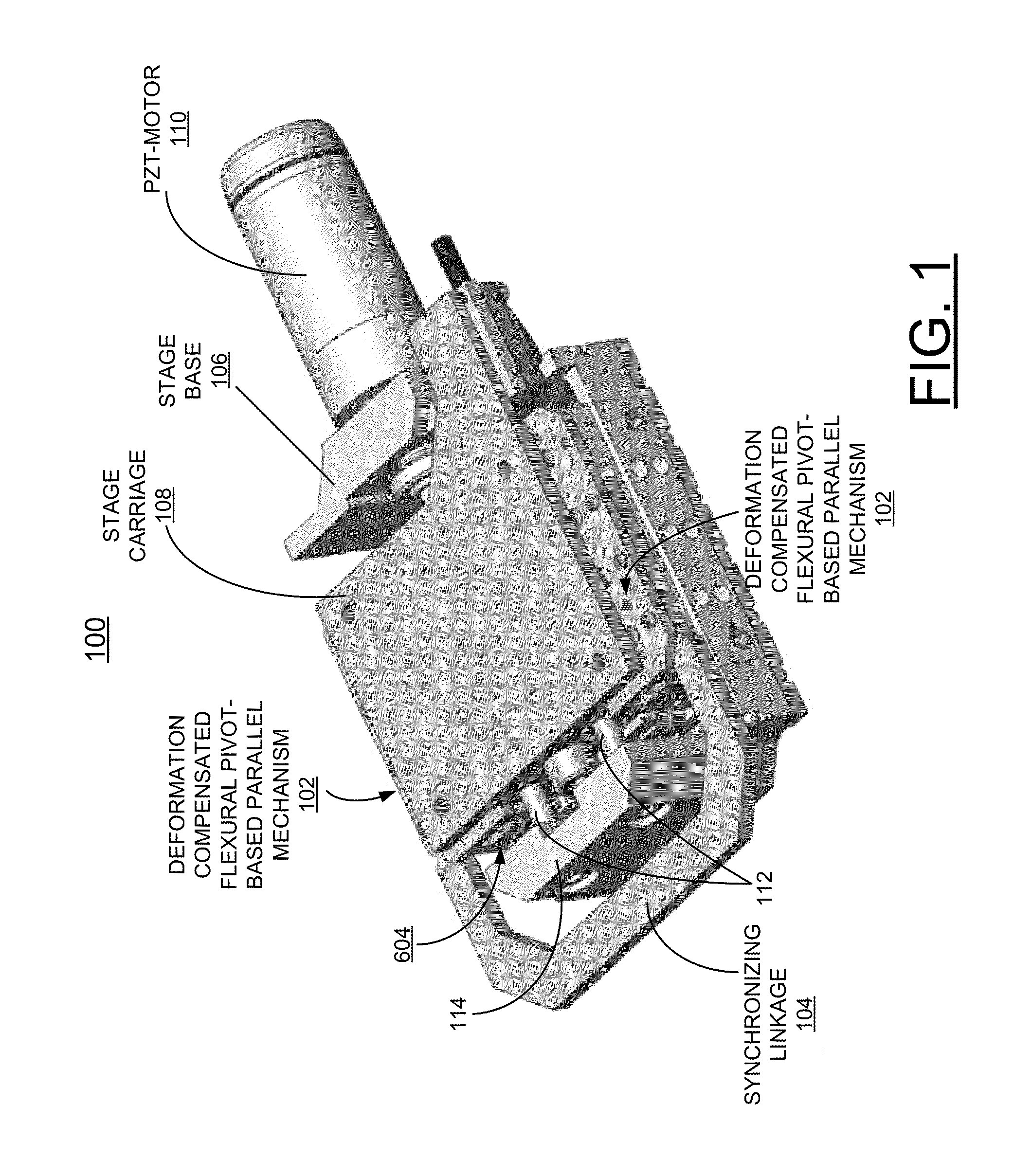
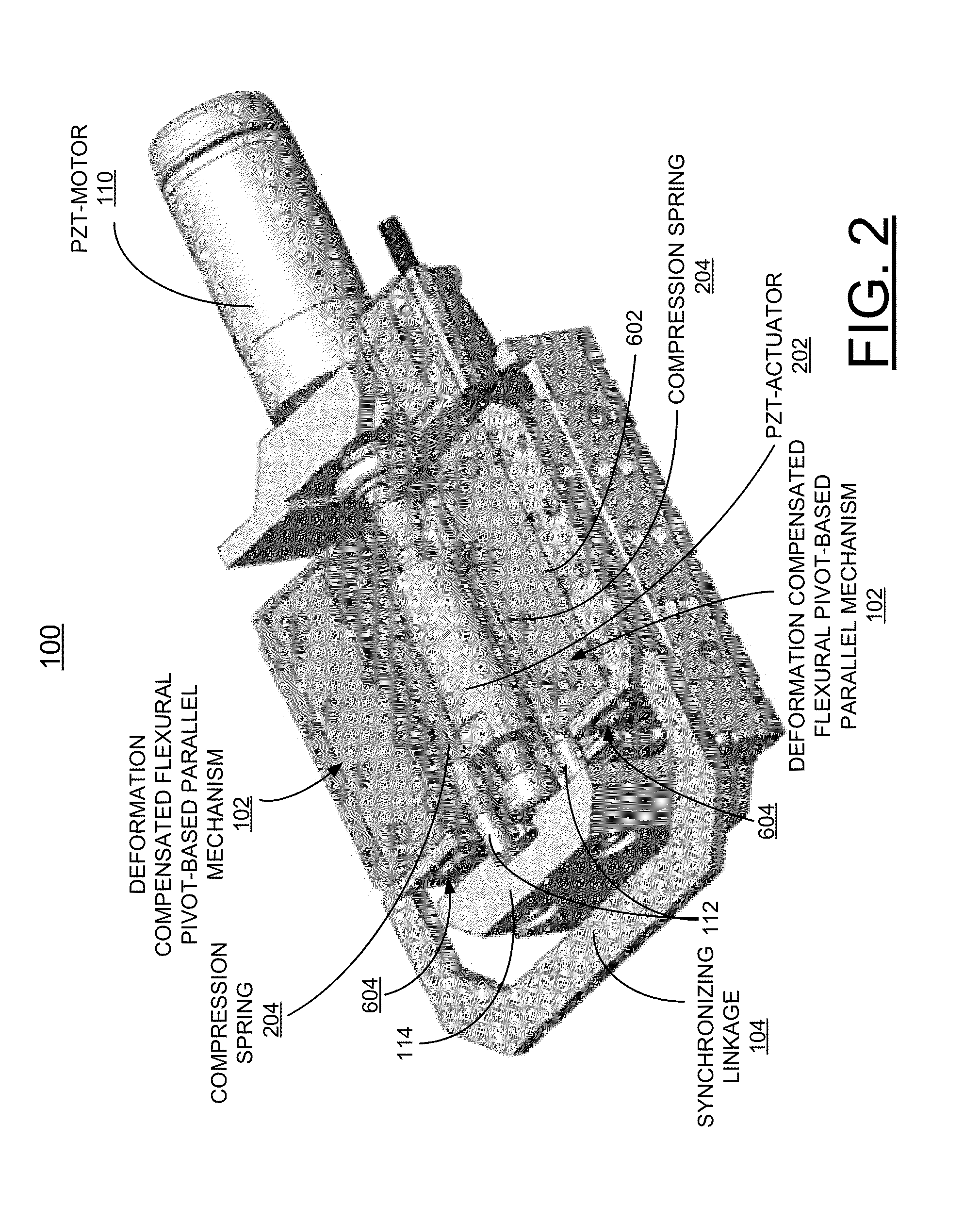
The patent describes a precision linear nanospositioning stage with high-resolution and smooth motion. It uses a deformation-compensated flexural linear guiding mechanism with minimal center shift errors. The stage has three sets of these mechanisms, two mounted vertically and one horizontally for better linear guiding and stiffness. It also includes a PZT motor and actuator for sub-nanometer positioning and a set of compression springs to minimize motion backlash. Overall, this invention allows for unparalleled accuracy and efficiency in nanopositioning.

Problems solved by technology

However, their positioning resolution is limited by the friction of the bearing-based guiding system.
Moreover, their linear motion straightness of trajectory usually is not repeatable due to the roundness errors of the bearings rolling element and the uncertainty of the rolling ball or roller sliding effect.

Method used


Image

  • Mechanical design of deformation compensated flexural pivots structured for linear nanopositioning stages
  • Mechanical design of deformation compensated flexural pivots structured for linear nanopositioning stages
  • Mechanical design of deformation compensated flexural pivots structured for linear nanopositioning stages

Examples


Embodiment Construction

[0026]In the following detailed description of embodiments of the invention, reference is made to the accompanying drawings, which illustrate example embodiments by which the invention may be practiced. It is to be understood that other embodiments may be utilized and structural changes may be made without departing from the scope of the invention.

[0027]The terminology used herein is for the purpose of describing particular embodiments only and is not intended to be limiting of the invention. As used herein, the singular forms “a”, “an” and “the” are intended to include the plural forms as well, unless the context clearly indicates otherwise. It will be further understood that the terms “comprises” and / or “comprising,” when used in this specification, specify the presence of stated features, integers, steps, operations, elements, and / or components, but do not preclude the presence or addition of one or more other features, integers, steps, operations, elements, components, and / or gr...


PUM


Abstract

A method and deformation compensated flexural pivots structured for precision linear nanopositioning stages are provided. A deformation-compensated flexural linear guiding mechanism includes a basic parallel mechanism including a U-shaped member and a pair of parallel bars linked to respective pairs of I-link bars and each of the I-bars coupled by a respective pair of flexural pivots. The basic parallel mechanism includes substantially evenly distributed flexural pivots minimizing center shift dynamic errors.

Description

CONTRACTUAL ORIGIN OF THE INVENTION[0001]The United States Government has rights in this invention pursuant to Contract No. DE-ACO2-06CH11357 between the United States Government and UChicago Argonne, LLC representing Argonne National Laboratory.FIELD OF THE INVENTION[0002]The present invention relates generally to precision positioning stage systems, and more particularly, relates to a method and deformation compensated flexural pivots structured for linear nanopositioning stages.DESCRIPTION OF THE RELATED ART[0003]Recently, there are more synchrotron radiation instrument applications that require a very high reproducibility for multidimensional linear positioning systems with nanometer or sub-nanometer resolution. In the travel range of less than a few hundred microns, commercial PZT-driven flexural linear stages are available.[0004]Commercial-precision ball-bearing-based or roller-bearing-based linear positioning stages are capable of providing a much larger travel range. However...

Claims


Application Information

Patent Timeline
IPC IPC(8): H02N2/04
CPCH02N2/04H10N30/50H10N30/20
Inventor SHU, DEMINGKEARNEY, STEVEN P.PREISSNER, CURT A.
Owner UCHICAGO ARGONNE LLC
Learn More