
Layout System Consisting of A Piezoactuator and A Flexible Circuit Board and Method for Assembling the Same

a flexible circuit board and piezoactuator technology, which is applied in the direction of generator/motor, mechanical vibration separation, instruments, etc., can solve the problems of high production cost, chance of short circuit, and the wrong orientation of the flexible circuit board b>3/b> at the outset cannot be corrected, etc., to achieve uniform pressing force, good mechanical connection, and good sealing

Active Publication Date: 2014-02-27
VEGA GRIESHABER GMBH & CO
View PDF6 Cites 4 Cited by
  • Summary
  • Abstract
  • Description
  • Claims
  • Application Information

AI Technical Summary

Benefits of technology

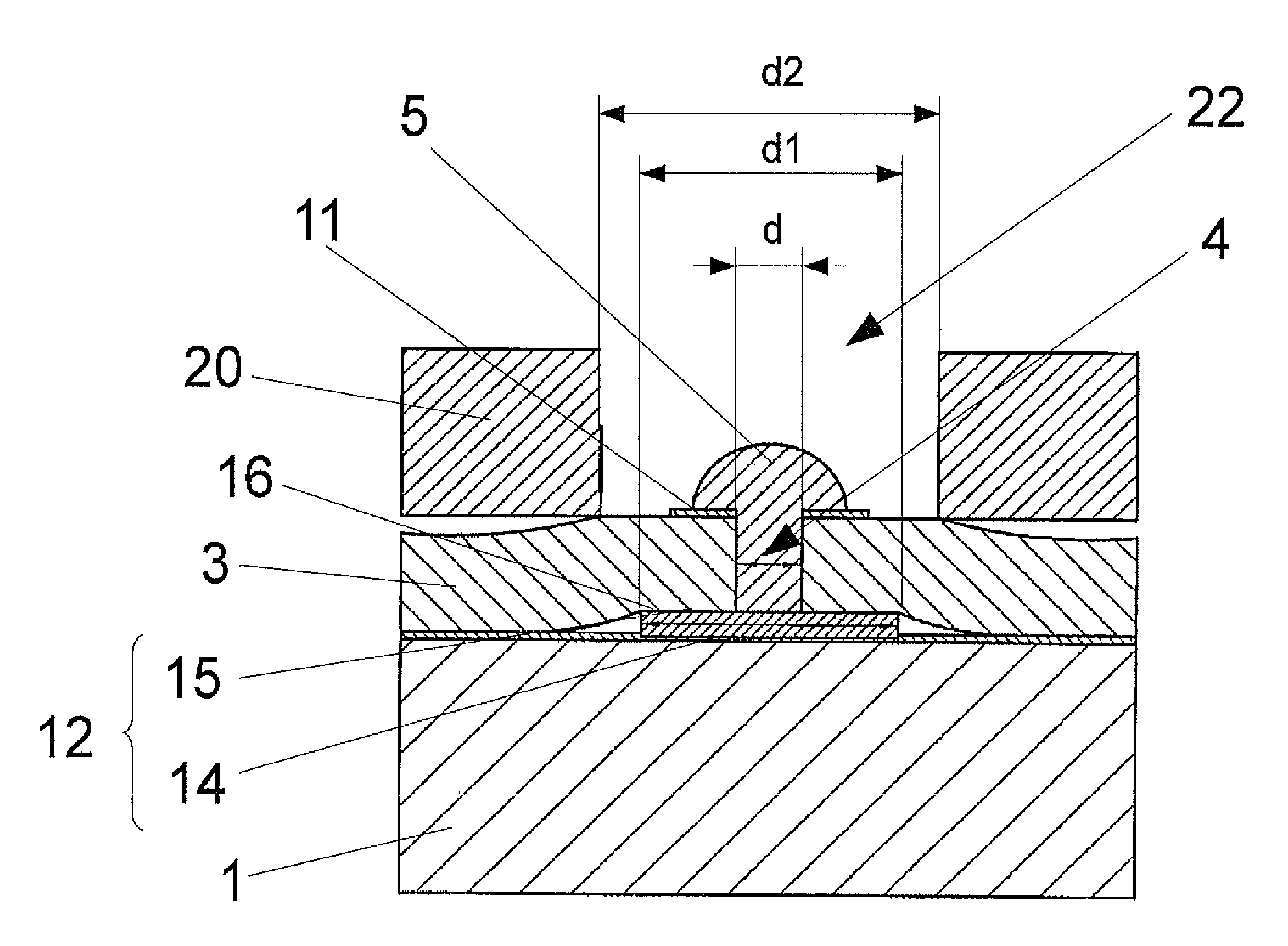
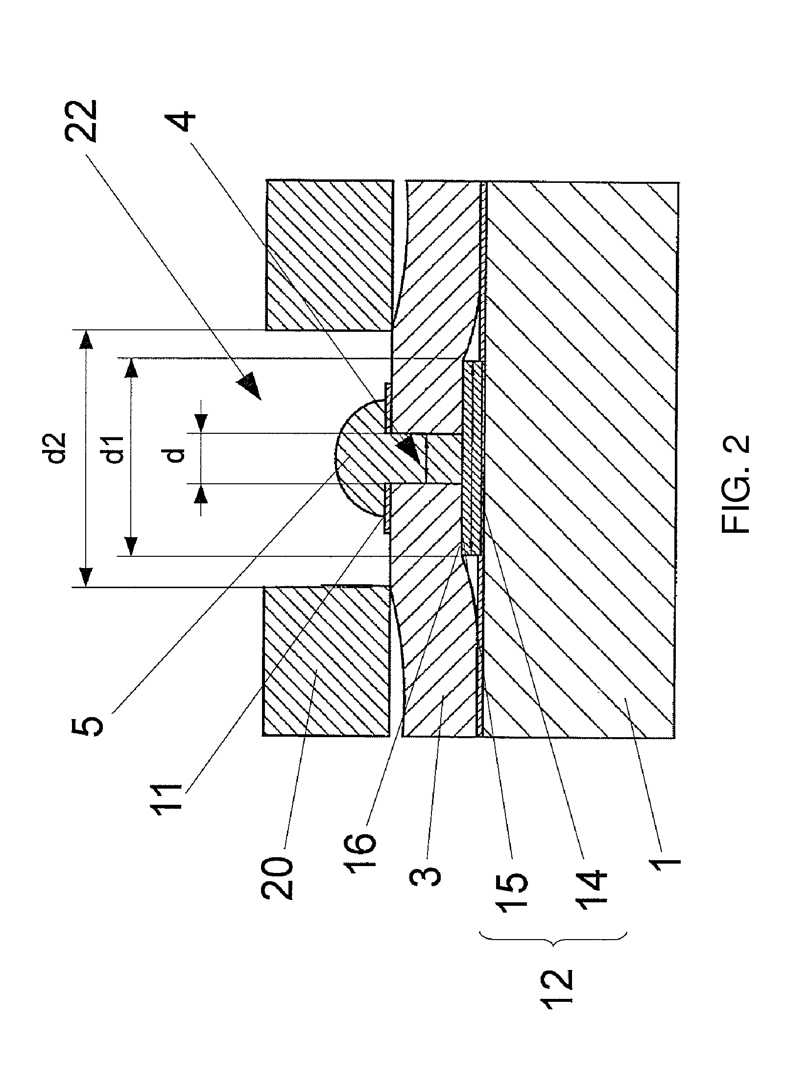
The invention provides a way to connect a piezoactuator to a flexible circuit board using a rivet-like glue connection, which increases mechanical stability compared to pure contact gluing. A thin-film electrode and a thick-film electrode are used, which helps to apply more force during the pressing together of the flexible circuit board and the piezoactuator. The installation aid makes it easy to produce the desired layout and prevents the adhesive from spreading and causing short circuits.

Problems solved by technology

An exactly reproducible dispensing of a very small quantity of a highly viscous medium can only be done with difficulty, due to the surface forces and temperature dependence prevailing in the case of small volumes, so that a higher production cost is the result.
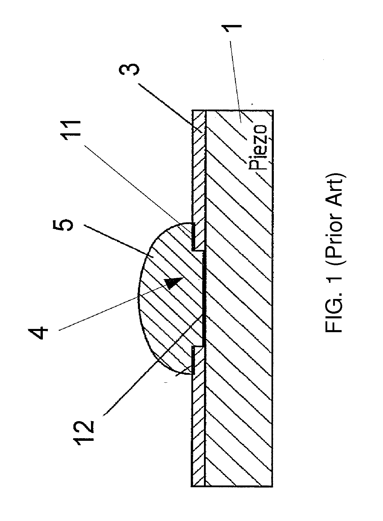
Furthermore, it is a problem with this procedure that a wrong orientation of the flexible circuit board 3 at the outset can no longer be corrected, since the conductive glue between the connection contacts 11, 12 will become smeared and again there is a chance of short circuits between the individual quadrants of the piezoactuator 1 or the correspondingly arranged contacts of the flexible circuit board 3.
This increases the risk of short circuits.
Thus, a mechanical loading of the glue connection is also only extremely slight.
For the above-presented reasons, a position correction afterwards is not possible.
In these layouts, however, there is still the drawback that the adhesive is first placed on the piezoactuator 1 and then the flexible circuit board 3 is pressed together with it, so that a subsequent correction of the orientation of the flexible circuit board 3 relative to the piezoactuator 1 is not possible.
As pointed out above, this effect leads to short circuits, resulting in a defective overall level meter layout.

Method used


Image

  • Layout System Consisting of A Piezoactuator and A Flexible Circuit Board and Method for Assembling the Same
  • Layout System Consisting of A Piezoactuator and A Flexible Circuit Board and Method for Assembling the Same
  • Layout System Consisting of A Piezoactuator and A Flexible Circuit Board and Method for Assembling the Same

Examples


Embodiment Construction

[0048]Reference will now be made in detail to embodiments of the invention. Wherever possible, same or similar reference numerals are used in the drawings and the description to refer to the same or like parts or steps. The drawings are in simplified form and are not to precise scale. The word ‘couple’ and similar terms do not necessarily denote direct and immediate connections, but also include connections through intermediate elements or devices. For purposes of convenience and clarity only, directional (up / down, etc.) or motional (forward / back, etc.) terms may be used with respect to the drawings. These and similar directional terms should not be construed to limit the scope in any manner. It will also be understood that other embodiments may be utilized without departing from the scope of the present invention, and that the detailed description is not to be taken in a limiting sense, and that elements may be differently positioned, or otherwise noted as in the appended claims wi...


PUM

PropertyMeasurementUnit
Forceaaaaaaaaaa
Flexibilityaaaaaaaaaa
Shapeaaaaaaaaaa

Abstract

A layout arrangement and system consisting of a piezoactuator and a flexible circuit board, with at least one electrical and mechanical connection, produced by an electrically conducting adhesive, between a first connection contact on the circuit board and a second connection contact on the piezoactuator, wherein the connection is led through an opening in the flexible circuit board and wherein the surfaces of the connection contacts that are glued together have an essentially parallel and equally oriented normal vector, and a method for assembling and arranging the same.

Description

CROSS-REFERENCE[0001]This Application claims the benefit of Provisional Application of U.S. Application No. 61 / 616,293, filed on Mar. 27, 2012, and entirety of which is hereby incorporated by reference.BACKGROUND OF THE INVENTION[0002]1. Field of the Invention[0003]The present invention relates to layout system consisting of a piezoactuator and a flexible circuit board, with at least one electrical and mechanical connection, produced by an electrically conducting adhesive, between a first connection contact on the flexible circuit board and a second connection contact on the piezoactuator, wherein the connection is led through an opening in the flexible circuit board and wherein the surfaces of the connection contacts that are glued together have an essentially parallel and equally oriented normal vector. Additionally, the present invention provides a method for assembling a piezoactuator and flexible circuit board to provide such a layout.[0004]2. Description of the Related Art[000...

Claims


Application Information

Patent Timeline
IPC IPC(8): H01L41/047H01L41/31
CPCH01L41/31H01L41/0475G10K11/004B06B1/06Y10T29/42H10N30/875H10N30/06H10N30/101H10N30/07
Inventor GRUHLER, HOLGEROHMAYER, GERD
Owner VEGA GRIESHABER GMBH & CO
Learn More