Electronic device with fan module

a technology of electronic devices and fan modules, applied in the direction of electrical equipment, electrical apparatus, electrical apparatus contruction details, etc., can solve the problems of reducing the heat dissipation efficiency of computers or severs

Inactive Publication Date: 2014-02-27
HON HAI PRECISION IND CO LTD
View PDF0 Cites 2 Cited by
  • Summary
  • Abstract
  • Description
  • Claims
  • Application Information

AI Technical Summary

Problems solved by technology

However, in a disorderly fashion, the cables will occupy a large space in the comput

Method used


Image

  • Electronic device with fan module
  • Electronic device with fan module
  • Electronic device with fan module

Examples


Embodiment Construction

[0010]The present disclosure, including the accompanying drawings, is illustrated by way of examples and not by way of limitation. It should be noted that references to “an” or “one” embodiment in this disclosure are not necessarily to the same embodiment, and such references mean at least one.

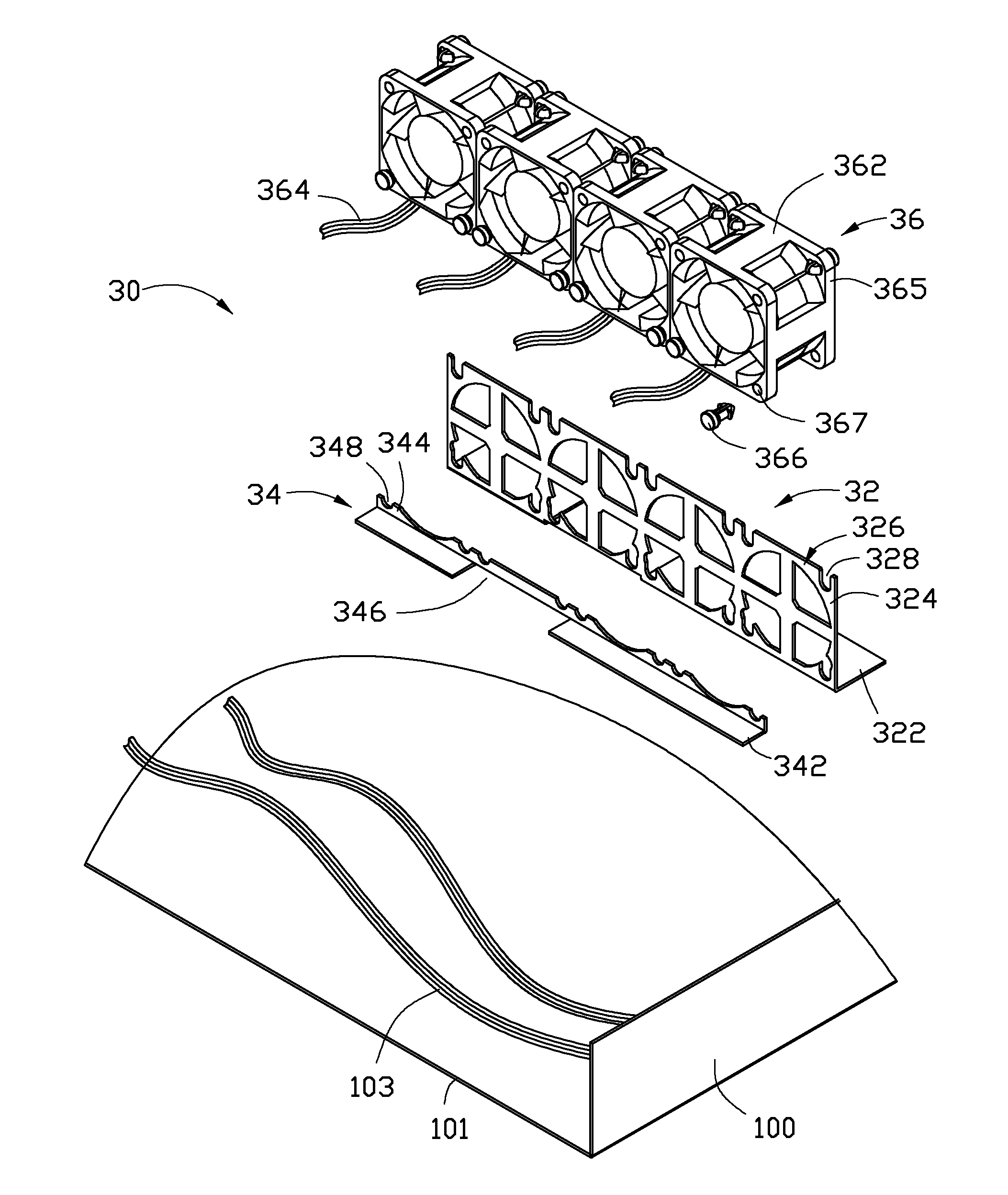
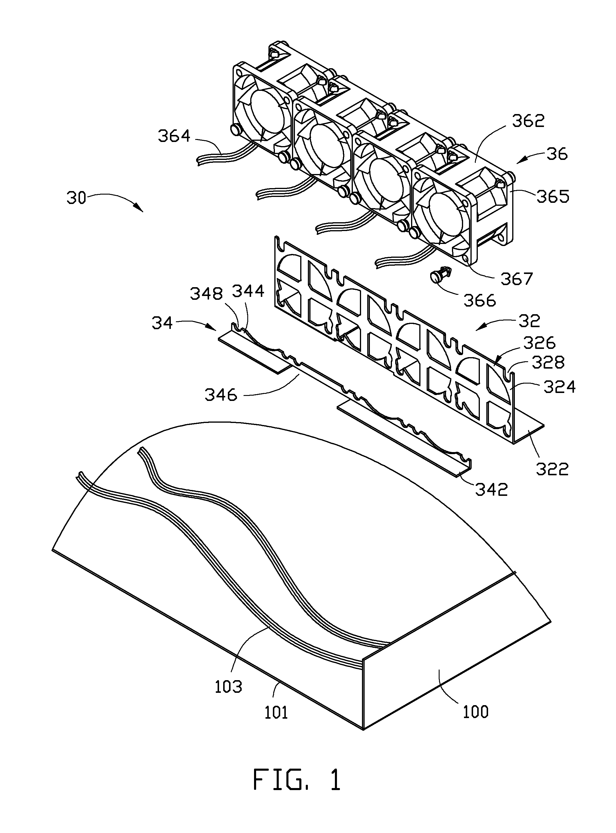
[0011]Referring to FIG. 1 and FIG. 2, an exemplary embodiment of an electronic device includes an enclosure 100 and a fan module 30. The enclosure 100 includes a sidewall 101 and a plurality of cables 103 received in the enclosure 100.

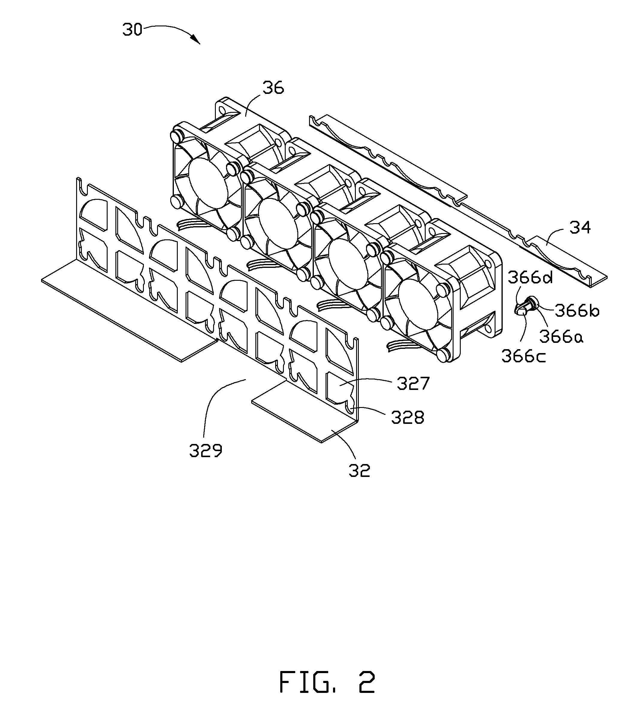
[0012]The fan module 30 includes a first support bracket 32, a second support bracket 34, and a plurality of fans 36.

[0013]The first support bracket 32 includes a first mounting plate 322 and a support plate 324 perpendicularly extending up from a side of the first mounting plate 322. A plurality of vent areas 326 is longitudinally formed on the support plate 324. Each vent area 326 defines a plurality of vents 327. The support plate 324 defines four slots 328, r...


PUM


Abstract

An electronic device includes a sidewall and a fan module. The fan module includes a first support bracket mounted on an inner surface of the sidewall, a second support bracket mounted on the inner surface of the sidewall and spaced from the first support bracket, and a number of fans sandwiched between the first support bracket and the second support bracket. The sidewall, the first support bracket, the second support bracket, and the fans cooperatively bound a receiving slot for receiving cables of the electronic device. The first and second support bracket each defines a cutout adjacent to the sidewall and communicating with the receiving slot for allowing some of the cables to extend out of the receiving slot.

Description

BACKGROUND[0001]1. Technical Field[0002]The present disclosure relates to electronic devices, and particularly, to an electronic device with a fan module.[0003]2. Description of Related Art[0004]A plurality of fans can be installed in the computers or servers to dissipate heat. The fans are electrically connected to power modules through cables. However, in a disorderly fashion, the cables will occupy a large space in the computers or servers, thus reducing heat dissipating efficiency of the computers or severs.BRIEF DESCRIPTION OF THE DRAWINGS[0005]Many aspects of the present embodiments can be better understood with reference to the following drawings. The components in the drawings are not necessarily drawn to scale, the emphasis instead being placed upon clearly illustrating the principles of the present embodiments. Moreover, in the drawings, all the views are schematic, and like reference numerals designate corresponding parts throughout the several views.[0006]FIG. 1 is an ex...

Claims


Application Information

Patent Timeline
IPC IPC(8): H05K7/20
CPCH05K7/20172H05K7/20727
Inventor SUN, ZHENG-HENG
Owner HON HAI PRECISION IND CO LTD
Why Eureka
Try Eureka