Method of making heat sink

a heat sink and heat sink technology, applied in the field of heat sinks, can solve the problems of increased cost of heat sinks, solder and flux, and overheating of electronic components,

Inactive Publication Date: 2009-10-08
FU ZHUN PRECISION IND SHENZHEN +1
View PDF5 Cites 4 Cited by
  • Summary
  • Abstract
  • Description
  • Claims
  • Application Information

AI Technical Summary

Problems solved by technology

If the heat is not timely removed, these electronic components may overheat.
However, solder and flux are required during soldering of the heat sink.
Thus, the cost of the heat sink is increased and the process of making the heat sink is complicated.
In addition, during the soldering process, tiny air bubbles will be formed between the fin assembly and the base, thereby increasing a heat resistance between the base and the fin assembly, which further decreases the heat dissipating efficiency of the heat sink.

Method used


Image

  • Method of making heat sink
  • Method of making heat sink
  • Method of making heat sink

Examples


first embodiment

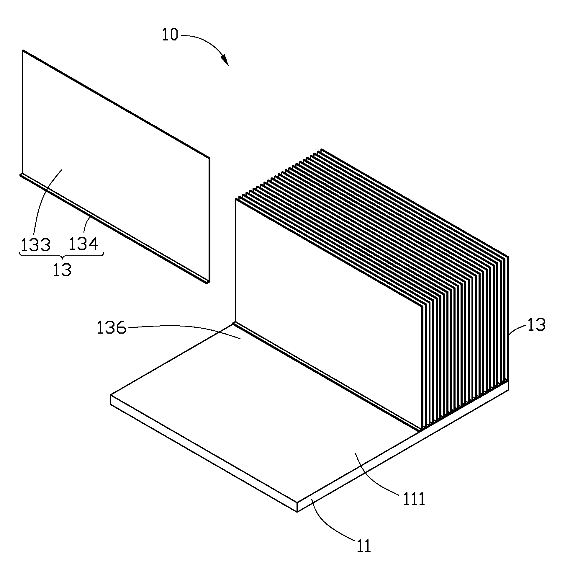
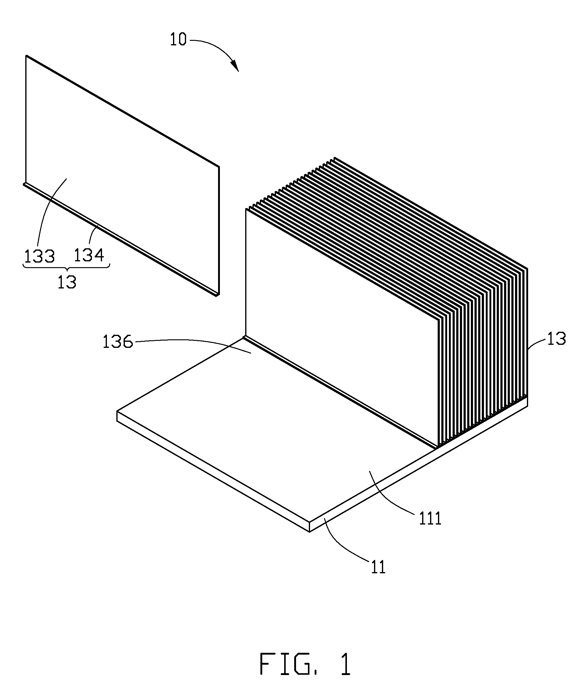
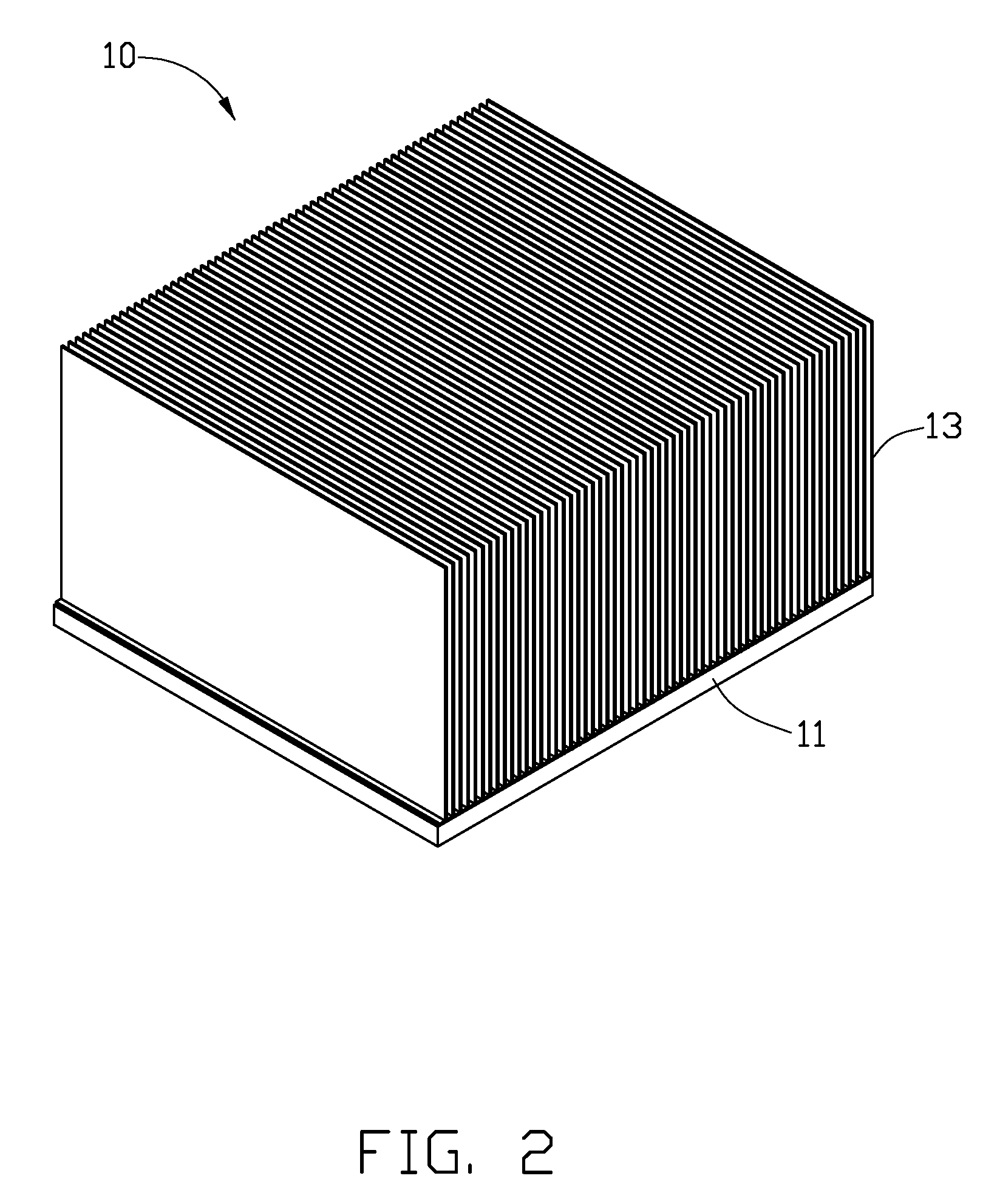
[0014]Referring to FIG. 1, an ultrasonic welding process of a heat sink 10 in accordance with the present invention is shown. Firstly, a base 11 and a plurality of individual fins 13 are provided.

[0015]The base 11 has a rectangular shape. The base 11 is made of copper, which has good thermal conductivity. The base 11 has a contacting surface 111 at a top thereof.

[0016]The fins 13 are made of aluminum, which has good thermal conductivity. Aluminum has a lower thermal conductivity than copper. Each fin 13 has a plate shape, and has a thickness in a range of 0.3˜0.4 mm. Each fin 13 includes a rectangular main body 133, and a flange 134 extending vertically and outwardly from a bottom side of the main body 133.

[0017]During assembly of the heat sink 10, the fins 13 are successively welded to the base 11 by ultrasonic welding method. Specifically, the flange 134 of each fin 13 is welded on the contacting surface 111 of the base 11 by the ultrasonic welding method. When one of the fins 13 ...

second embodiment

[0021]Referring to FIG. 3, an ultrasonic welding process of a heat sink 20 in accordance with the present invention is shown. Firstly, a base 21 and a plurality of individual fins 23 are provided.

[0022]The base 21 has a cylindrical shape. The base 21 is made of copper, which has good thermal conductivity. The base 21 has a circular contacting surface 211 at a circumference thereof.

[0023]The fins 23 are made of aluminum, which has good thermal conductivity. Each fin 23 has a plate shape, and has a thickness in a range of 0.3˜0.4 mm. Each fin 23 includes a main body 233, and a flange 234 extending vertically and outwardly from an inner side of the main body 233. The main body 233 of each fin 23 includes a lower part 237, a middle part 238 and an upper part 239. A length from an inner side towards an outer side of each of the lower part 237, the middle part 238 and the upper part 239 is successively increased, thereby forming two sidesteps at an outer side of the main body 233.

[0024]Du...


PUM

PropertyMeasurementUnit
shapeaaaaaaaaaa
cylindrical shapeaaaaaaaaaa
lengthaaaaaaaaaa

Abstract

A method of making a heat sink (10) includes the following steps: providing a base (11) and a plurality of individual fins (13), and welding the fins successively to the base by ultrasonic welding method.

Description

BACKGROUND[0001]1. Technical Field[0002]The present invention generally relates to heat sinks, and more particularly to a method of making a heat sink used for dissipating heat from heat-generating components.[0003]2. Description of Related Art[0004]It is well known that heat is produced by electronic components such as integrated circuit chips during their normal operations. If the heat is not timely removed, these electronic components may overheat. Therefore, heat sinks are often used to cool these electronic components.[0005]Presently, a typical heat sink includes a base and a fin assembly attached to the base. The base thermally contacts with a heat generating electronic component. The fin assembly includes a plurality of fins joined together. The fin assembly is welded to the base via tin soldering method. However, solder and flux are required during soldering of the heat sink. Specially, when the base and the fin assembly are respectively made of different materials, such as ...

Claims


Application Information

Patent Timeline
Patent Type & Authority Applications(United States)
IPC IPC(8): B21D53/02
CPCB23K20/10B23K20/2333B23K2201/14B23K2201/36B23K2203/10B23K2203/12Y10T29/4935H01L21/4882H01L23/3672H01L2924/0002B23K2203/18H01L2924/00B23K2101/14B23K2101/36B23K2103/10B23K2103/12B23K2103/18
Inventor GUO, QING-LEIZHU, SHOU-LI
Owner FU ZHUN PRECISION IND SHENZHEN
Why Eureka
Try Eureka