Heat dissipation assembly

a technology of heat dissipation assembly and heat sink, which is applied in the direction of lighting, heating apparatus, and semiconductor/solid-state device details. it can solve the problems of reducing the heat dissipation efficiency of the heat sink, and the heat generated by the central processing unit (cpus) of the computer or server

Inactive Publication Date: 2013-07-04
HONG FU JIN PRECISION IND (SHENZHEN) CO LTD +1
View PDF5 Cites 0 Cited by
  • Summary
  • Abstract
  • Description
  • Claims
  • Application Information

AI Technical Summary

Problems solved by technology

Central processing units (CPUs) of computers or servers generate a large amount of heat during operation.
However, the heat sink includes a plurality of parallel and spaced fins for the air to quickly flow through, the air cannot fully contact with the fins, thus reducing heat dissipating efficiency of the heat sink.

Method used


Image

  • Heat dissipation assembly
  • Heat dissipation assembly
  • Heat dissipation assembly

Examples


Embodiment Construction

[0010]The present disclosure, including the accompanying drawings, is illustrated by way of examples and not by way of limitation. It should be noted that references to “an” or “one” embodiment in this disclosure are not necessarily to the same embodiment, and such references mean at least one.

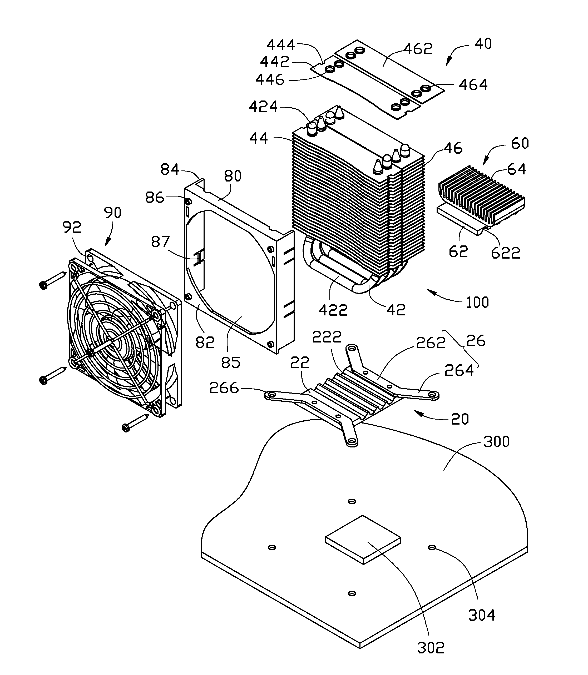
[0011]Referring to FIG. 1, an embodiment of a heat dissipation assembly 100 for dissipating heat of an electronic component 302 mounted on a motherboard 300 includes a base 20, a first heat sink 40, a second heat sink 60, a bracket 80, and a fan 90. The motherboard 300 defines four fastening holes 304 adjacent to four corners of the electronic component 302. In the embodiment, the electronic component 302 is a central processing unit.

[0012]The base 20 includes a bottom wall 22 and two substantially U-shaped fixing plates 26 fixed to two opposite ends of the bottom wall 22. The bottom wall 22 defines four receiving slots 222 parallel to the ends of the bottom wall 22, between the fixing plates ...


PUM


Abstract

A heat dissipation assembly includes a base, two heat pipes, a first heat sink, and a fan. The first heat sink includes a first fin assembly installed to one of the heat pipe, and a second fin assembly installed to the other heat pipe. The fan is installed to the first fin assembly opposite to the second fin assembly. The first fin assembly includes a plurality of first fins spaced from and parallel to one another. The second fin assembly includes a plurality of second fins spaced from and parallel to one another. The first fins are misaligned with the second fins. Each heat pipe is mounted to the base, and extends through the first or second fins.

Description

BACKGROUND[0001]1. Technical Field[0002]The present disclosure relates to a heat dissipation assembly.[0003]2. Description of Related Art[0004]Central processing units (CPUs) of computers or servers generate a large amount of heat during operation. The heat needs to be dissipated immediately to ensure the continued proper functioning of the computers or servers. Presently, a heat sink is mounted on a CPU for dissipating the heat, and a cooling fan is installed to the heat sink for generating airflow. However, the heat sink includes a plurality of parallel and spaced fins for the air to quickly flow through, the air cannot fully contact with the fins, thus reducing heat dissipating efficiency of the heat sink.BRIEF DESCRIPTION OF THE DRAWINGS[0005]Many aspects of the embodiments can be better understood with reference to the drawings. The components in the drawings are not necessarily drawn to scale, the emphasis instead being placed upon clearly illustrating the principles of the em...

Claims


Application Information

Patent Timeline
Patent Type & Authority Applications(United States)
IPC IPC(8): F28D15/00
CPCG06F1/20H01L23/3672H01L23/427H01L23/467H01L2924/0002H01L21/4882H01L2924/00
Inventor HE, JING-YA
Owner HONG FU JIN PRECISION IND (SHENZHEN) CO LTD
Why Eureka
Try Eureka