
Battery module

a battery module and battery technology, applied in the field of batteries, can solve the problem of insufficient adhesive strength between the flexible shell and the supporting seat, and achieve the effects of enhancing the connection strength, reducing the heat dissipation efficiency, and further promoting the cooling performance of the battery modul

Inactive Publication Date: 2010-11-25
AMITA TECH
View PDF3 Cites 31 Cited by
  • Summary
  • Abstract
  • Description
  • Claims
  • Application Information

AI Technical Summary

Benefits of technology

[0012]Compared to the prior arts, the invention has the following advantageous functions. Firstly, the drawback of the prior secondary battery, which an insufficiently adhesive strength exists between the flexible shell and the supporting seat, can be solved by thermally pressing the adhesive layer of the extending part to be adhered to the supporting seat, such that the flexible shell is connected securely onto the supporting seat and the connecting strength is enhanced surely. Secondly, another drawback of the fixing structure of the prior secondary battery, which the cause of the reduction of the heat-dissipating efficiency comes from too small heat-transferring area formed by the double-sided tapes, can be solved by the adaptation of the invention. Thirdly, by designing a structure where the extending part of the flexible shell is exposed, the heat generated by the battery cell can be carried away by an external air flown into the supporting seat, such that the cooling performance of the battery module can be further promoted.

Problems solved by technology

Firstly, the drawback of the prior secondary battery, which an insufficiently adhesive strength exists between the flexible shell and the supporting seat, can be solved by thermally pressing the adhesive layer of the extending part to be adhered to the supporting seat, such that the flexible shell is connected securely onto the supporting seat and the connecting strength is enhanced surely.

Method used


Image

  • Battery module
  • Battery module
  • Battery module

Examples


Embodiment Construction

[0024]In cooperation with attached drawings, the technical contents and detailed description of the present invention are described thereinafter according to a number of preferable embodiments, not used to limit its executing scope. Any equivalent variation and modification made according to appended claims is all covered by the claims claimed by the present invention.

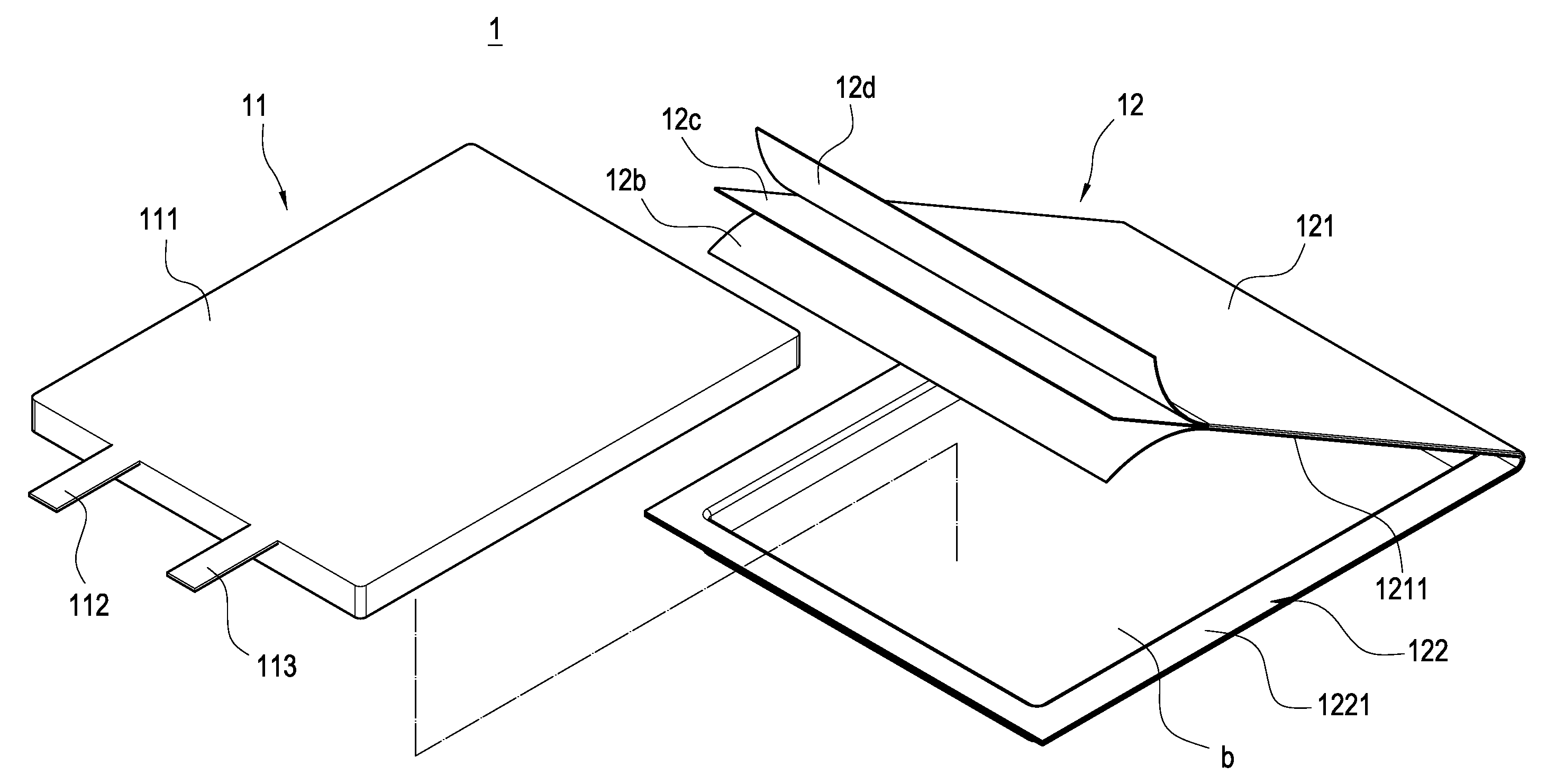
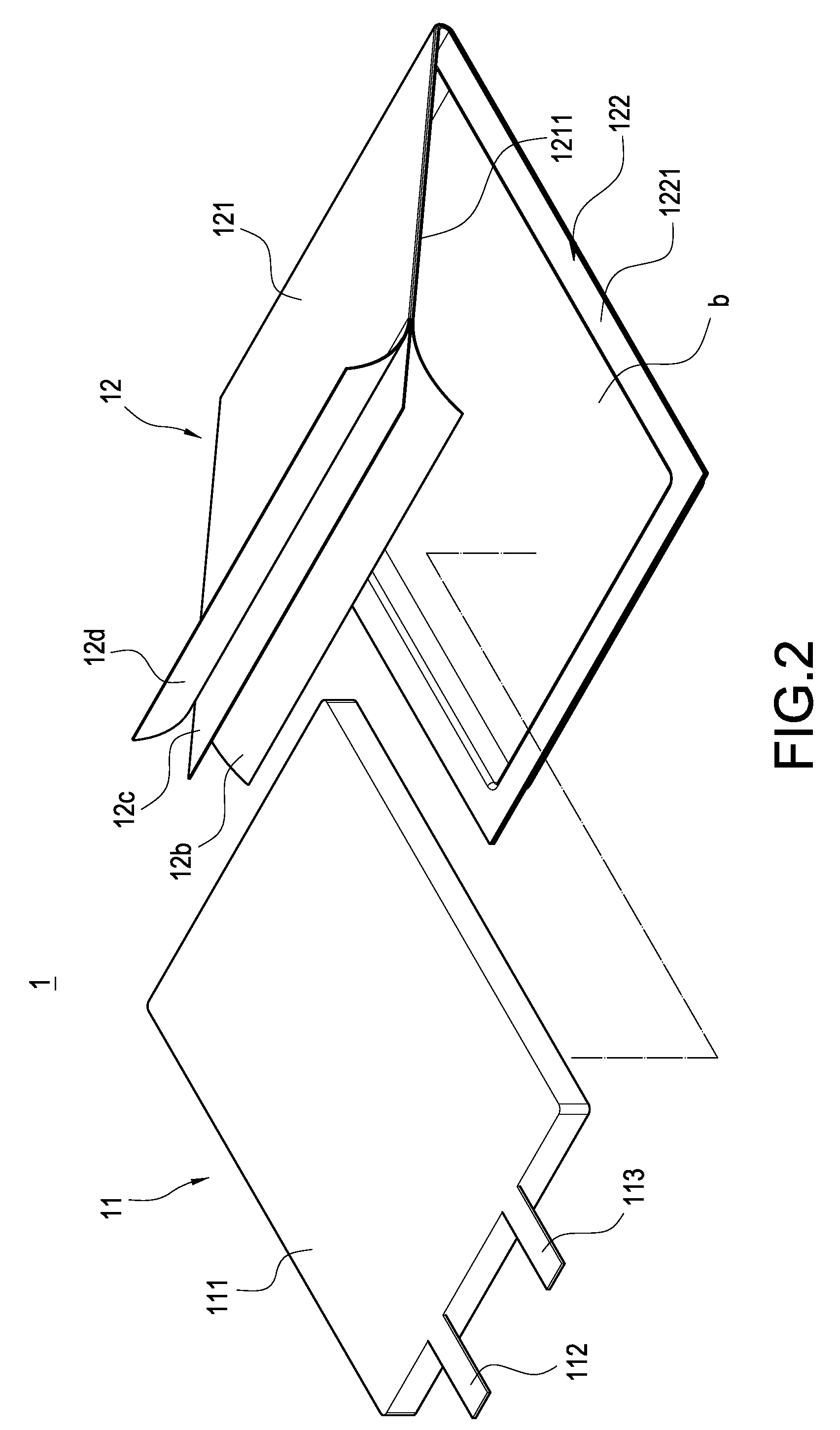
[0025]Please refer to FIG. 2, showing a perspective explosive view of the invention. Also, refer to FIG. 7 together. The invention is to provide a battery module 1, including a battery cell 11, a flexible shell 12 and a supporting seat 20.

[0026]The battery cell 11 has a main body 111 and two electrodes 112, 113 extended outwardly from the main body 111. These two electrodes 112, 113 respectively are a positive electrode 112 and a negative electrode 113 interspaced with the positive electrode 112. In this embodiment, the main body 111 is a thin cuboid shown as a plate shape, but not limited to this configuration only. T...


PUM

PropertyMeasurementUnit
flexibleaaaaaaaaaa
adhesiveaaaaaaaaaa
lengthaaaaaaaaaa

Abstract

A battery module includes a battery cell, a flexible shell and a supporting seat. The battery cell has a main body and two electrodes extended outwardly from the main body; the flexible shell has an upper and lower lid plates, both of which are connected and cooperated to each other to envelop the battery cell, and which are provided for the electrodes to extend out and respectively have an upper and lower adhesive parts, both of which are adhered to each other; and, the supporting seat is provided for arranging the flexible shell, in which the flexible shell further has an extending part, which is extended from one of the upper, lower adhesive parts towards the supporting seat and has an adhesive layer adhered to the supporting seat by a thermal pressing process, such that the flexible shell and the supporting seat can be connected securely.

Description

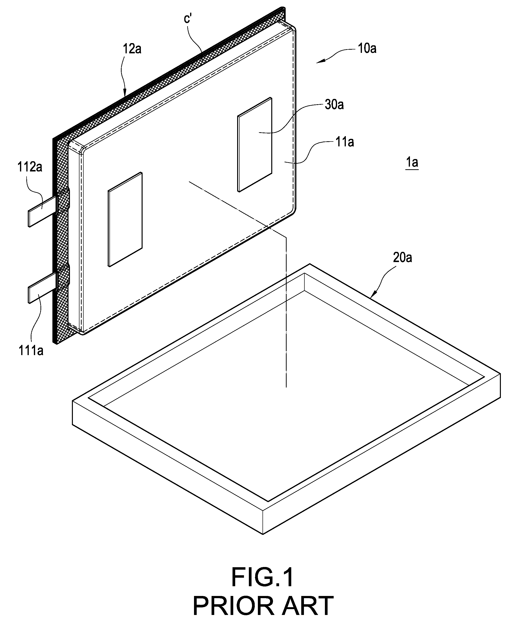
BACKGROUND OF THE INVENTION[0001]1. Field of the Invention[0002]The present invention in general relates to a battery module, and in particular, to a battery module adaptable for electronic device.[0003]2. Description of Prior Art[0004]Currently, secondary battery has already applied to common portable electronic devices comprehensively, for example, mobile phone, digital camera, notebook computer, etc. However, following the trends that the sizes of these portable electronic devices are shrunk and the using time is prolonged, the power of the secondary battery adopted by these devices is increased, whereby there is more waste heat generated from the secondary battery. Therefore, improving the heat dissipation of the secondary battery has become an issue intended to be addressed by each manufacturer urgently.[0005]Please refer to FIG. 1, showing a perspective explosive view of the fixing structure of a prior secondary battery. This prior secondary battery 1a includes a battery cell ...

Claims


Application Information

Patent Timeline
Patent Type & Authority Applications(United States)
IPC IPC(8): H01M2/02H01M50/119H01M50/121H01M50/129H01M50/136H01M50/55H01M50/557
CPCH01M2/021H01M2/0212H01M2/0275H01M2/0287Y02E60/50H01M6/46H01M8/0289H01M10/0436H01M2/1061Y02E60/10H01M50/557H01M50/124H01M50/121H01M50/129H01M50/136H01M50/55H01M50/119
Inventor CHEN, CHIN-MING
Owner AMITA TECH
Learn More