
Optical fiber cable network and method of construction of an optical fiber cable network

Inactive Publication Date: 2014-02-27
NEW MEDIA CO LTD
View PDF2 Cites 0 Cited by
  • Summary
  • Abstract
  • Description
  • Claims
  • Application Information

AI Technical Summary

Benefits of technology

The patent is about a new way to manage optical fiber cables in a network, which reduces the amount of unused dark fibers and makes it easier to design the network. This is done by using segments of the unused fibers for transmitting optical signals, which helps avoid waste. The cables can also have the same number of cores, making it easier to design the network, and there is no need to connect cables with different numbers of cores at the drop use closures, which simplifies the connection work.

Problems solved by technology

However, since optical fiber cables with different numbers of optical fiber cores are laid, there were the problems that design of the optical fiber cable network was difficult and, further, core management also became complicated.
The connection work at the time of laying the cables becomes complicated, so conversely the cost sometimes rose.
Further, when there was a change in the number or positions of optical receivers in a region, separate optical fiber cables had to be laid and therefore handling was difficult.

Method used


Image

  • Optical fiber cable network and method of construction of an optical fiber cable network
  • Optical fiber cable network and method of construction of an optical fiber cable network
  • Optical fiber cable network and method of construction of an optical fiber cable network

Examples


Embodiment Construction

[0039]Below, the attached figures will be referred to so as to explain the embodiments of the present invention. In the following embodiments, the same or similar members are assigned common reference signs.

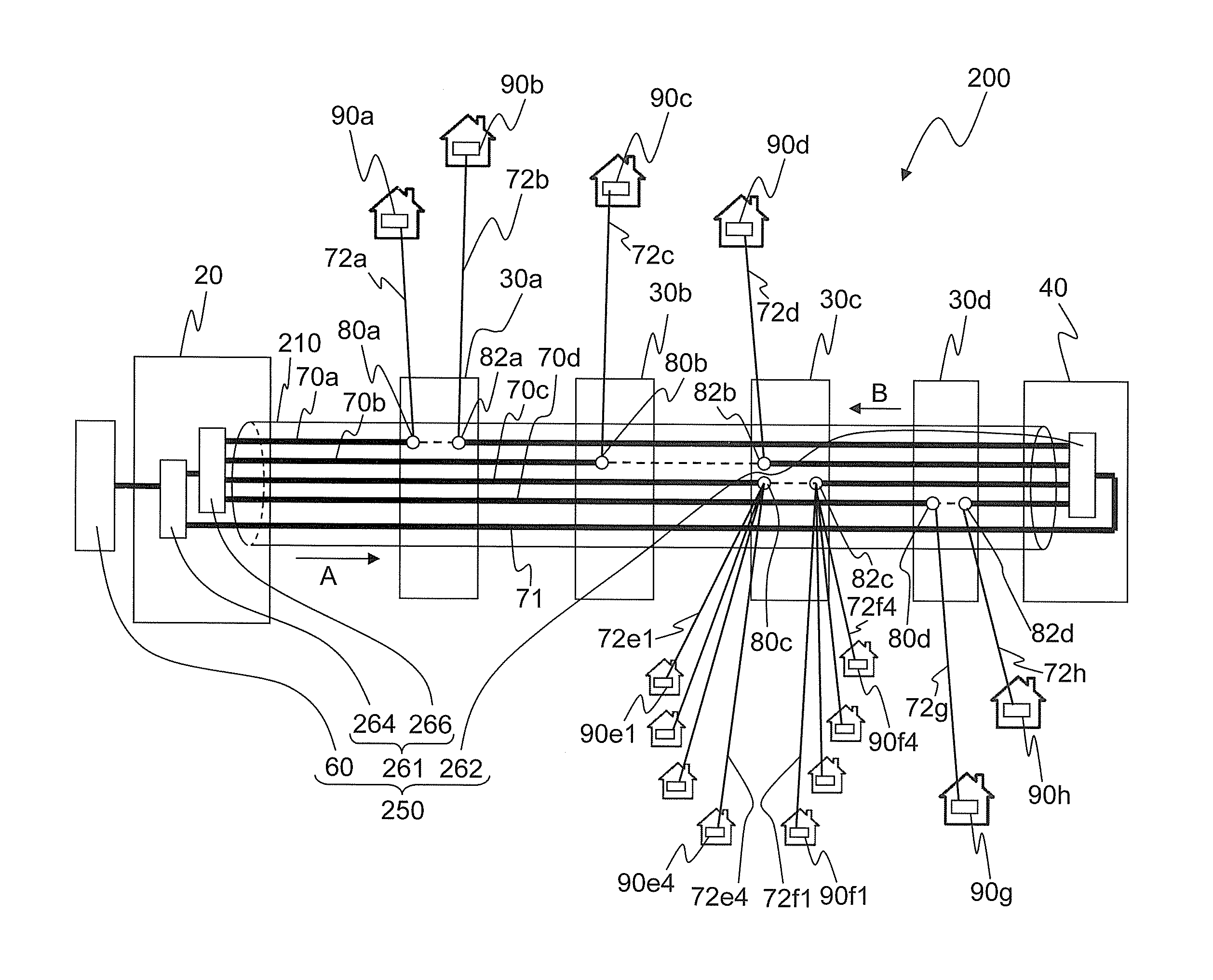
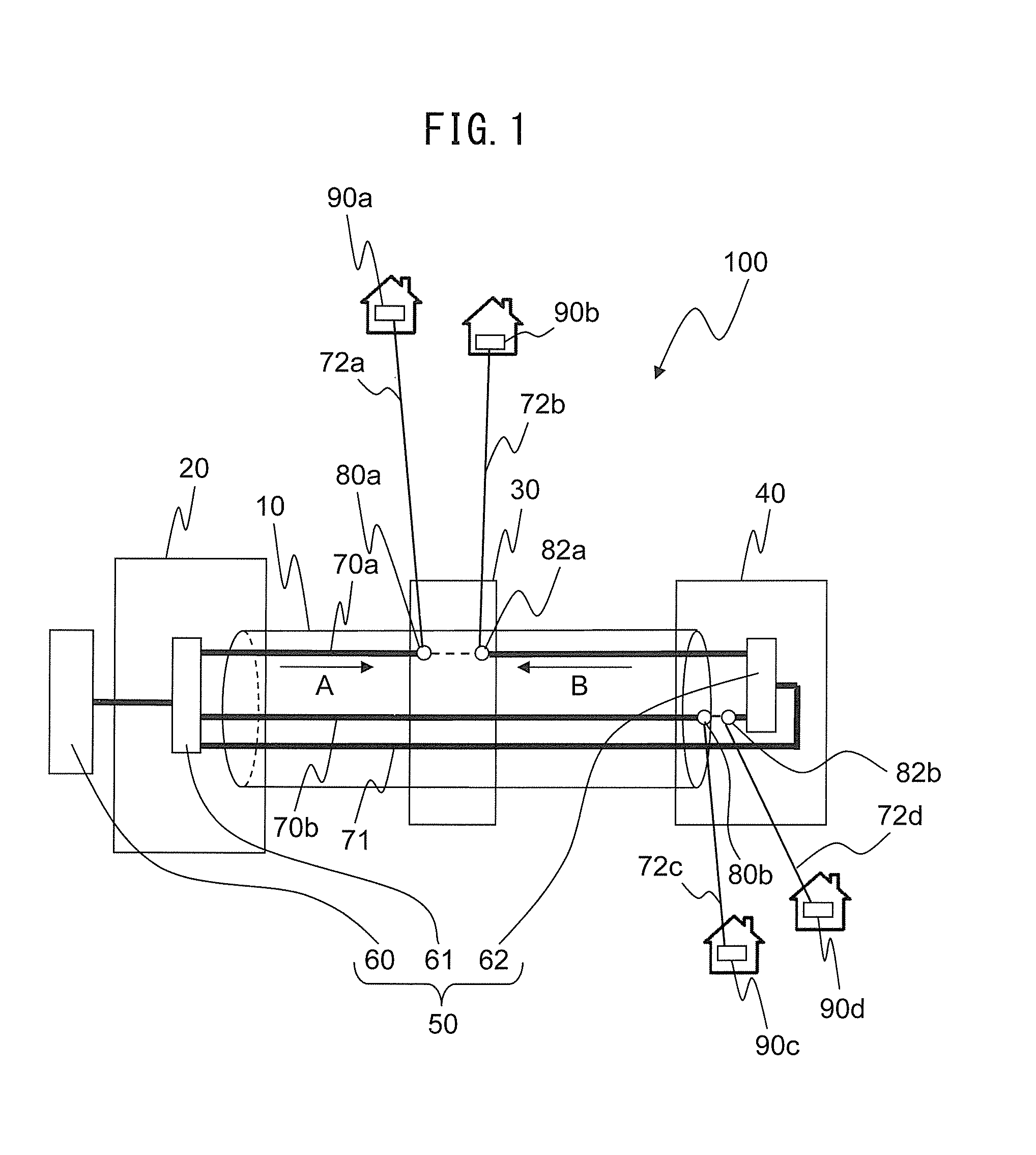
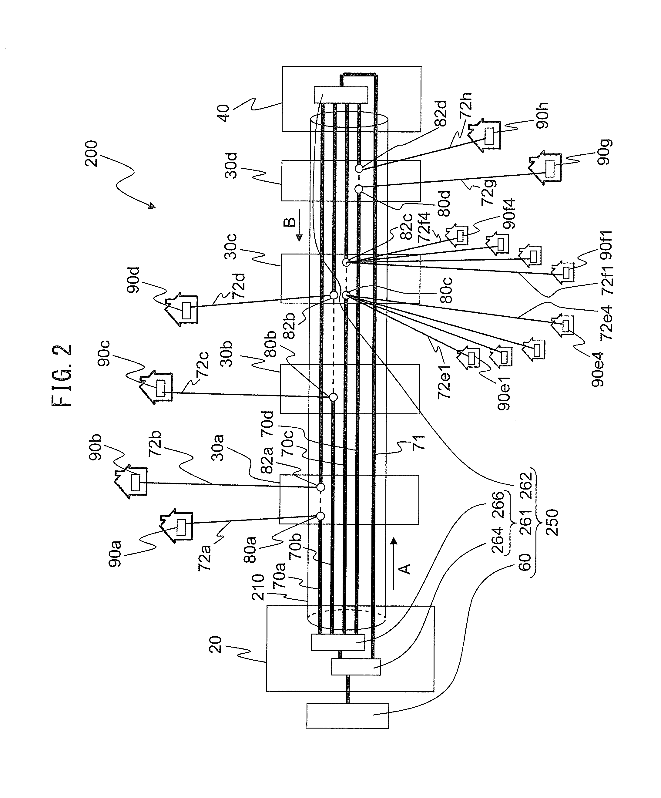
[0040]FIG. 1 is a view of the configuration which shows an example of an optical fiber cable network according to one embodiment of the present invention. The optical fiber cable network 100 of the illustrated embodiment is provided with an optical fiber cable 10 which has three optical fiber cores 70a, 70b, and 71 which transmit an optical signal, an optical signal device 50 which is connected to the two ends of the optical fiber cores 70a and 70b, and first splitters 80a and 80b (one brancher) and second splitters 82a and 82b (other branchers) which are provided at the optical fiber cores 70a and 70b and branch optical signals. The optical signal device 50 is provided with an optical transmitter 60 which transmits an optical signal, a first distributor 61 which connects the opt...


PUM


Abstract

An optical fiber cable network and method of construction of an optical fiber cable network. An optical fiber cable network 100 is provided with an optical fiber cable 10 which has a plurality of optical fiber cores 70a, 70b, and 71 which transmit an optical signal, an optical signal device 50 which is connected to the two ends of the optical fiber cores 70a and 70b among the plurality of optical fiber cores, and two branchers 80a and 80b which are provided at least at one of the optical fiber cores and branching the optical signal, one brancher 80a of the two branchers branching the optical signal from the optical signal device at one end side and the other brancher 80b branching the optical signal from the optical signal device at the other end side.

Description

BACKGROUND OF THE INVENTION[0001]1. Field of the Invention[0002]The present invention relates to an optical fiber cable network which uses a multicore optical fiber cable and a method of construction of an optical fiber cable network.[0003]2. Description of the Related Art[0004]In recent years, optical fiber cables have come to be utilized for distribution of broadcasts or communication in a predetermined region. Optical fiber cable networks have come to be newly constructed.[0005]A conventional optical fiber cable network will be explained using FIG. 3. FIG. 3 is a view of the configuration which shows an example of the case of constructing an optical fiber cable network 300 by using a multicore optical fiber cable 310. The illustrated optical fiber cable network 300 is constructed so as to transmit an optical signal which is transmitted from an optical signal device 350 to eight homes in a predetermined region. The homes are set with optical receivers 390a to 390h. The optical rec...

Claims


Application Information

Patent Timeline
IPC IPC(8): G02B6/44
CPCG02B6/4479G02B6/4495Y10T29/49826G02B6/4431
Inventor HARADA, SHIGEYOSHIARASHIDA, TERUAKI
Owner NEW MEDIA CO LTD
Learn More