
Vertical centrifugal separation apparatus and method of recovering centrifuged liquid

Active Publication Date: 2012-06-28
TOMOE ENGINEERING CO LTD
View PDF9 Cites 1 Cited by
  • Summary
  • Abstract
  • Description
  • Claims
  • Application Information

AI Technical Summary

Benefits of technology

[0015]In the vertical centrifugal separation apparatus according to the present invention, the liquid to be processed is supplied from the lower portion of the cylindrical rotational tube which rotates about the vertical axis, and the centrifuged liquid is discharged and recovered from the upper portion of the cylindrical rotational tube in performing centrifugation. When the centrifugation is stopped for cleaning the cylindrical rotational tube, for example, the cylindrical rotational tube is set to a first overturn position to recover the remaining centrifuged liquid, and then the cylindrical rotational tube is set to a second overturn position to pull the tube out of the casing. With such a structure, the vertical centrifugal separation apparatus according to the present invention can recover the centrifuged liquid as the target with a reduced loss and without waste.

Problems solved by technology

The vertical centrifugal separation apparatus, however, is inconvenient in performing cleaning operation of the bowl.
It is thus difficult to remove the bowl in some of the installation places of the apparatus.
For example when a liquid (centrifuged liquid) centrifuged through centrifugation is a target, the liquid remaining in the bowl represents a loss each time the bowl is pulled out of the casing in the vertical centrifugal separation apparatus disclosed in Patent Document 1, although this is not recognized as a problem when a target is centrifuged solid matter.
For example, in the food, drug, medical item, and biotechnology-related fields, the manufacturing unit price or the cost of the centrifuged liquid may be significantly high.

Method used


Image

  • Vertical centrifugal separation apparatus and method of recovering centrifuged liquid
  • Vertical centrifugal separation apparatus and method of recovering centrifuged liquid
  • Vertical centrifugal separation apparatus and method of recovering centrifuged liquid

Examples


Embodiment Construction

[0029]A vertical centrifugal separation apparatus according to a preferred embodiment of the present invention will hereinafter be described in detail with reference to the accompanying drawings. However, the technical scope of the present invention should not be construed limitedly by the embodiment described below.

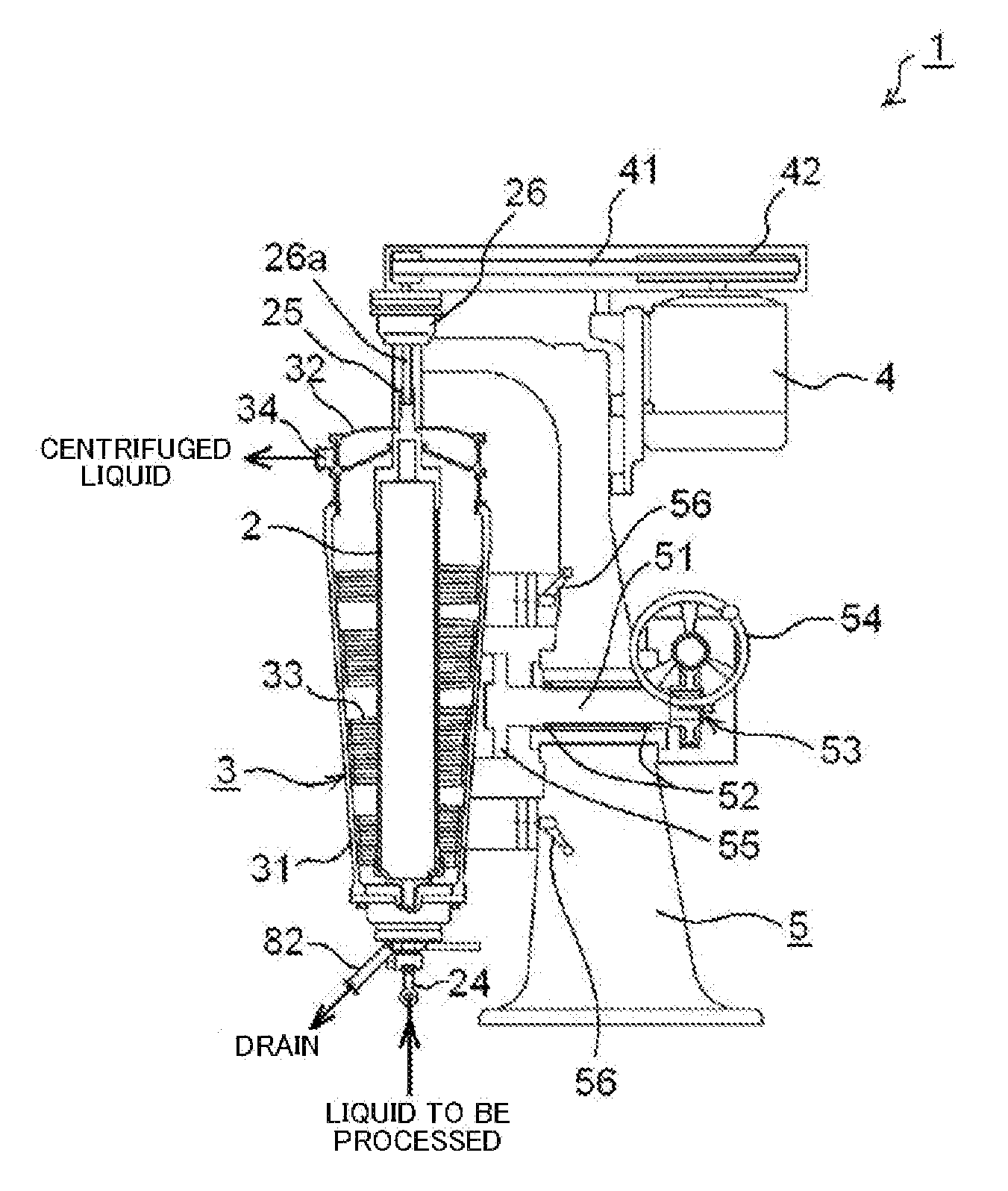
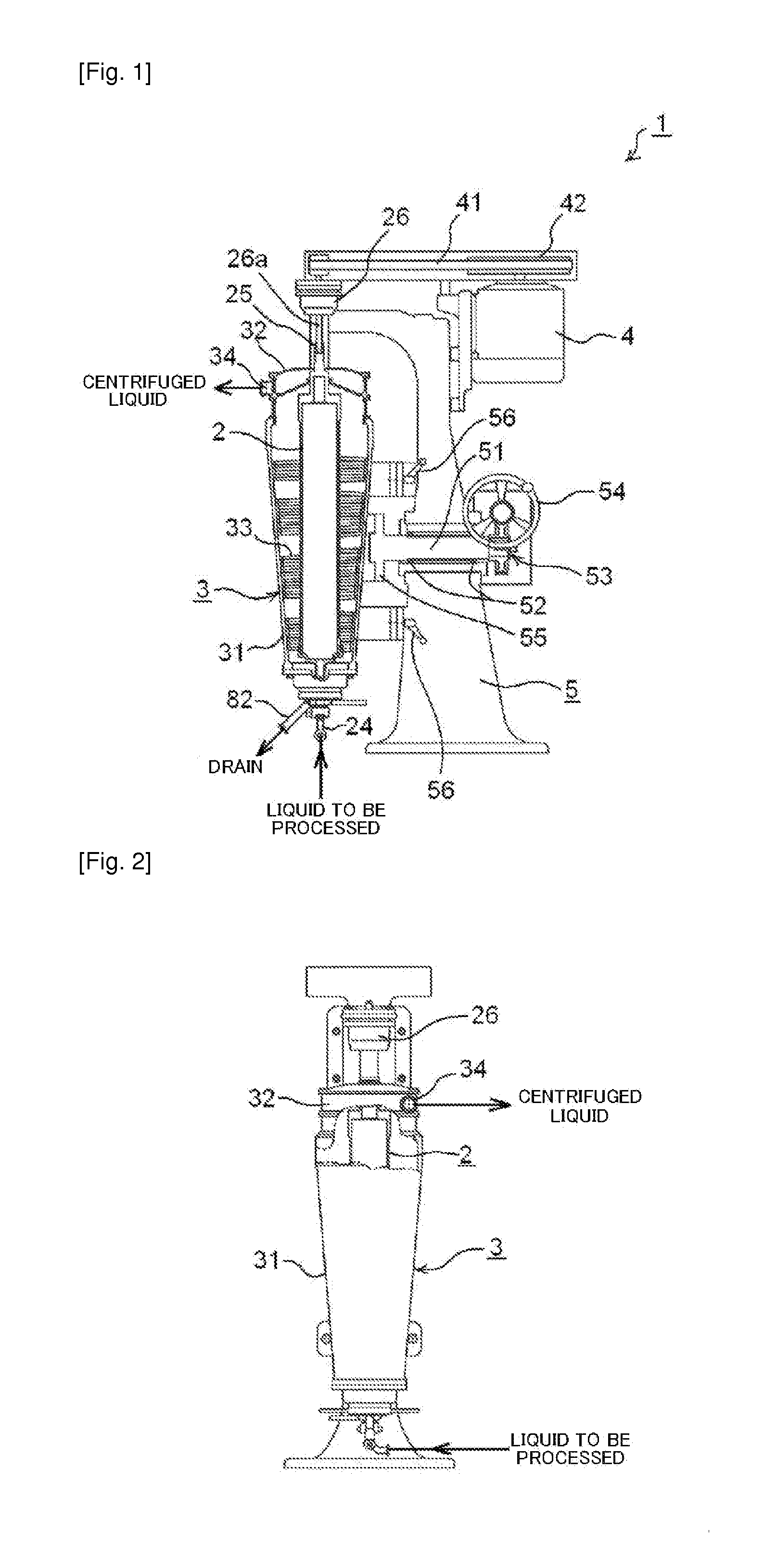
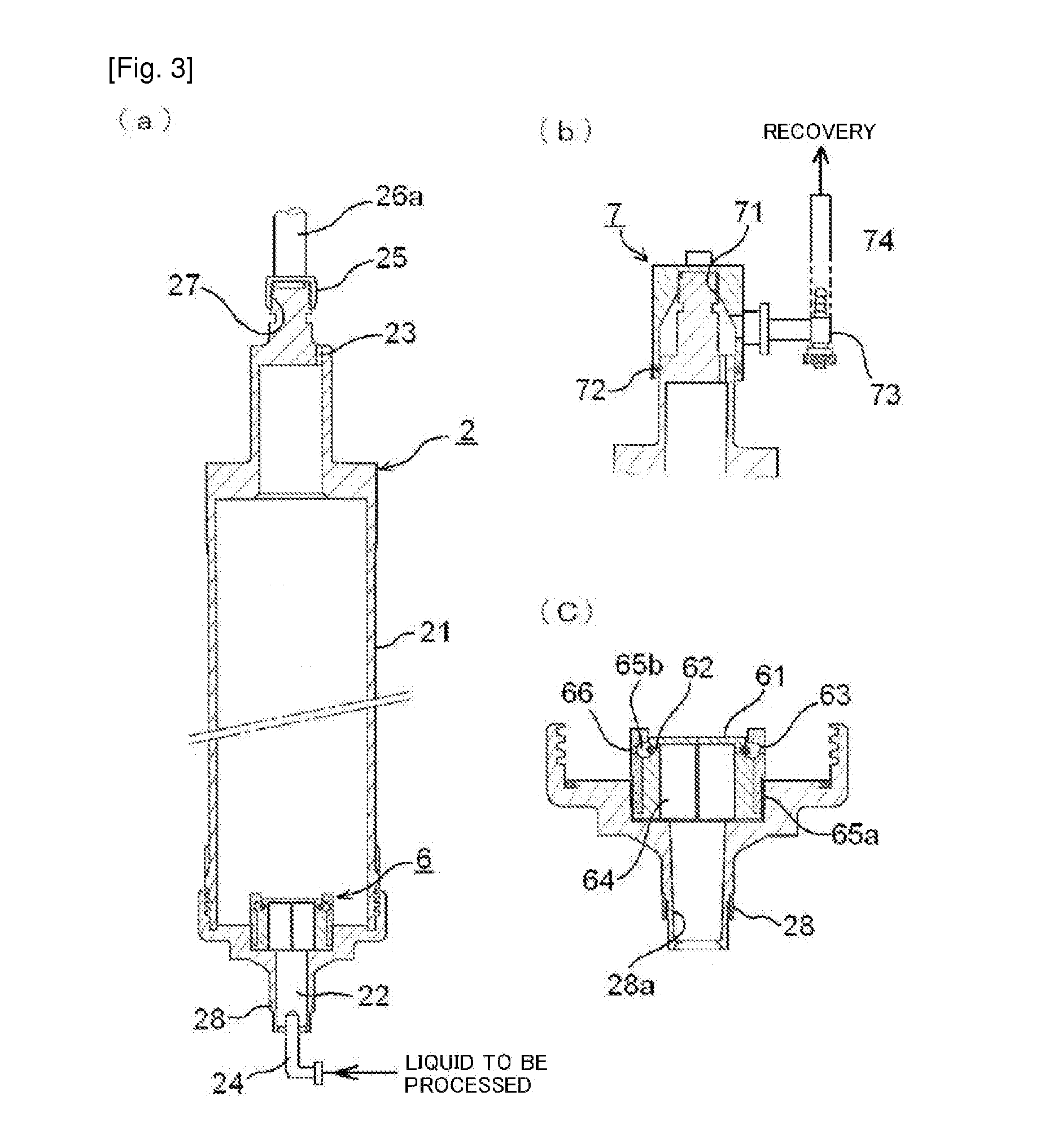
[0030]FIG. 1 is a longitudinal section view showing the vertical centrifugal separation apparatus according to the embodiment, and FIG. 2 is a front view showing the vertical centrifugal separation apparatus. FIG. 3 is a longitudinal section view showing a bowl, FIG. 4 is a perspective view showing a self-sealing apparatus, and FIG. 5 is a longitudinal section view showing a lower bearing.

[0031]As shown in FIGS. 1 and 2, the vertical centrifugal separation apparatus 1 according to the embodiment includes the bowl 2 which is a cylindrical rotational tube placed in a vertical direction, a casing 3 which serves as an exterior body for rotatably accommodating the bowl 2, a d...


PUM

PropertyMeasurementUnit
Angleaaaaaaaaaa
Centrifugal forceaaaaaaaaaa
Diameteraaaaaaaaaa

Abstract

To provide a vertical centrifugal separation apparatus which recovers a centrifuged liquid with a reduced loss and is suitable for when a target is the centrifuged liquid, and a method of recovering the centrifuged liquid. In performing centrifugation, the liquid to be processed is supplied from a lower portion of a cylindrical rotational tube which rotates about a vertical axis, and the centrifuged liquid is discharged and recovered from an upper portion of the cylindrical rotational tube. When the centrifugation is stopped for cleaning the cylindrical rotational tube, for example, the cylindrical rotational tube is set to a first overturn position to recover the remaining centrifuged liquid, and then the cylindrical rotational tube is set to a second overturn position to pull the tube out of the casing. Such a structure allows the recovery of the centrifuged liquid as the target with a reduced loss and without waste.

Description

TECHNICAL FIELD[0001]The present invention relates to a vertical centrifugal separation apparatus and a method of recovering a centrifuged liquid, and more particularly, to a vertical centrifugal separation apparatus suitable for centrifugation when a target is a centrifuged liquid and to a method of recovering the centrifuged liquid.BACKGROUND ART[0002]Centrifugal separation apparatuses are a type of apparatus which supplies a liquid to be processed containing solid matter into a rotating bowl and gives a centrifugal force to the liquid to be processed to allow separation thereof such as solid-liquid separation, liquid-liquid separation, and solid-liquid-liquid separation depending on the purpose. The centrifugal separation apparatus is widely used in various industrial fields without limitation.[0003]The centrifugal separation apparatuses include vertical centrifugal separation apparatuses in which a bowl is rotated about a vertical axis as a rotation axis and horizontal centrifug...

Claims


Application Information

Patent Timeline
IPC IPC(8): B04B7/04B01D17/00
CPCB04B11/04B04B7/04
Inventor TSUGAWA, TETSUYADOHI, KOKICHISADA, ATSUSHI
Owner TOMOE ENGINEERING CO LTD
Learn More