
Infrastructure diagnostic system and method

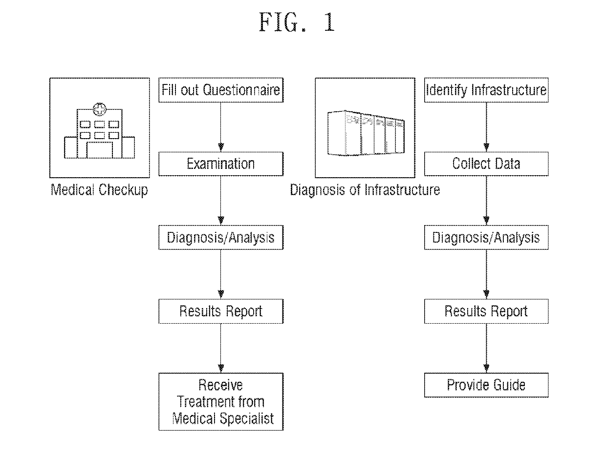
a technology for infrastructure and diagnostic system, applied in the field of infrastructure diagnostic system and method, can solve the problems of difficult to run infrastructure stably and efficiently, most small-to-medium-sized companies do not have the expertise to install or operate infrastructure, and provide limited one-time diagnostics, etc., to achieve efficient and stably management, without wasting money and tim

Active Publication Date: 2019-11-26
SAMSUNG SDS CO LTD
View PDF23 Cites 0 Cited by
  • Summary
  • Abstract
  • Description
  • Claims
  • Application Information

AI Technical Summary

Benefits of technology

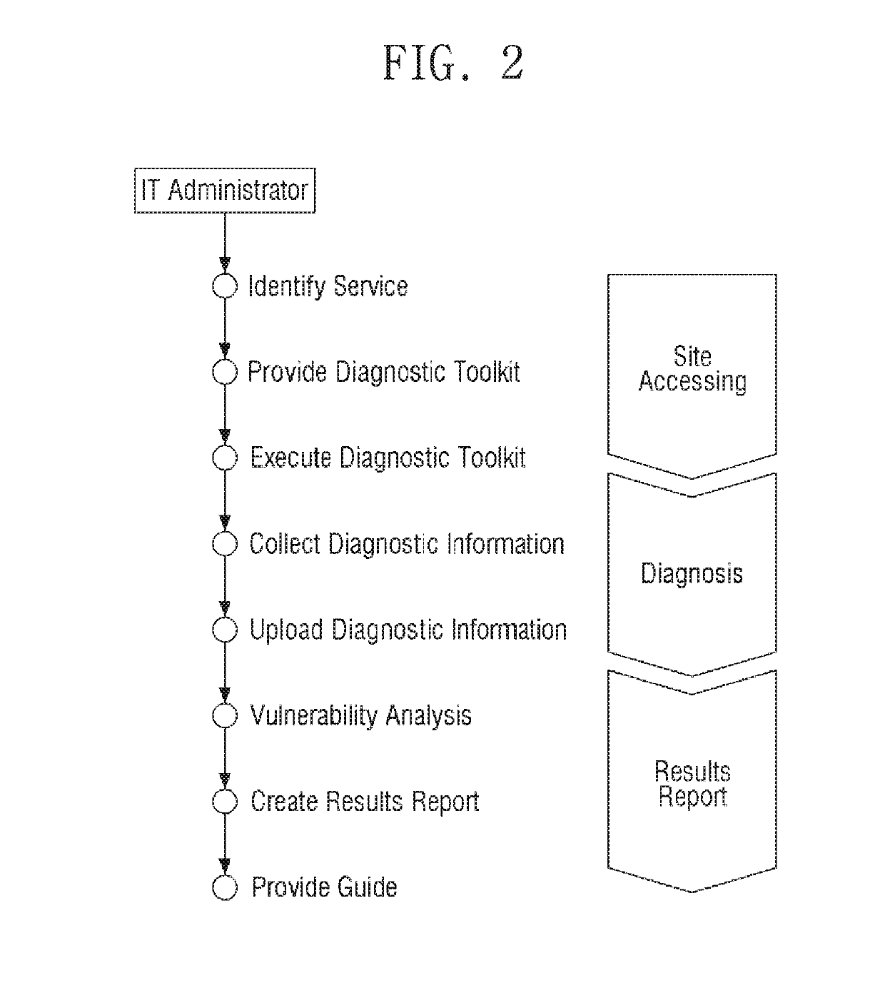
The present disclosure provides a free diagnostic tool for inspecting the infrastructure of small and medium-size companies. This tool helps identify vulnerabilities in each server of the company's infrastructure and provides a guide for addressing them. This results in efficient and stable management of the infrastructure, with no time and space constraints and no waste of money and time. Comprehensive diagnostics can be provided for various products from various suppliers, and each company can manage their own history of diagnosis.

Problems solved by technology

However, most small- to medium-size companies do not have the expertise to install or operate IT infrastructure.
Therefore, it is difficult to run IT infrastructure stably and efficiently.
For example, if faults or external attacks occur in their IT infrastructure, companies often ask an equipment supplier or a separate consulting firm to deal with the faults or the external attacks.
The equipment supplier, however, mostly provides limited one-time diagnostics only for a specific area.
Since the scope of this type of diagnostics is limited, it is difficult to provide analysis from an integrative perspective, especially when various servers are used, because each of the various servers needs to be diagnosed.
However, offline diagnostics involves collecting data on-site, analyzing the collected data, and making plans or suggestions based on the results of the analysis and thus has disadvantages in terms of time and space.

Method used


Image

  • Infrastructure diagnostic system and method
  • Infrastructure diagnostic system and method
  • Infrastructure diagnostic system and method

Examples


Embodiment Construction

[0026]Advantages and features of the present invention and methods of accomplishing the same may be understood more readily by reference to the following detailed description of preferred embodiments and the accompanying drawings. The present invention may, however, be embodied in many different forms and should not be construed as being limited to the embodiments set forth herein. Rather, these embodiments are provided so that this disclosure will be thorough and complete and will fully convey the concept of the invention to those skilled in the art, and the present invention will only be defined by the appended claims. Like reference numerals refer to like elements throughout the specification.

[0027]The terminology used herein is for the purpose of describing particular embodiments only and is not intended to be limiting of the invention. As used herein, the singular forms “a”, “an” and “the” are intended to include the plural forms as well, unless the context clearly indicates ot...


PUM


Abstract

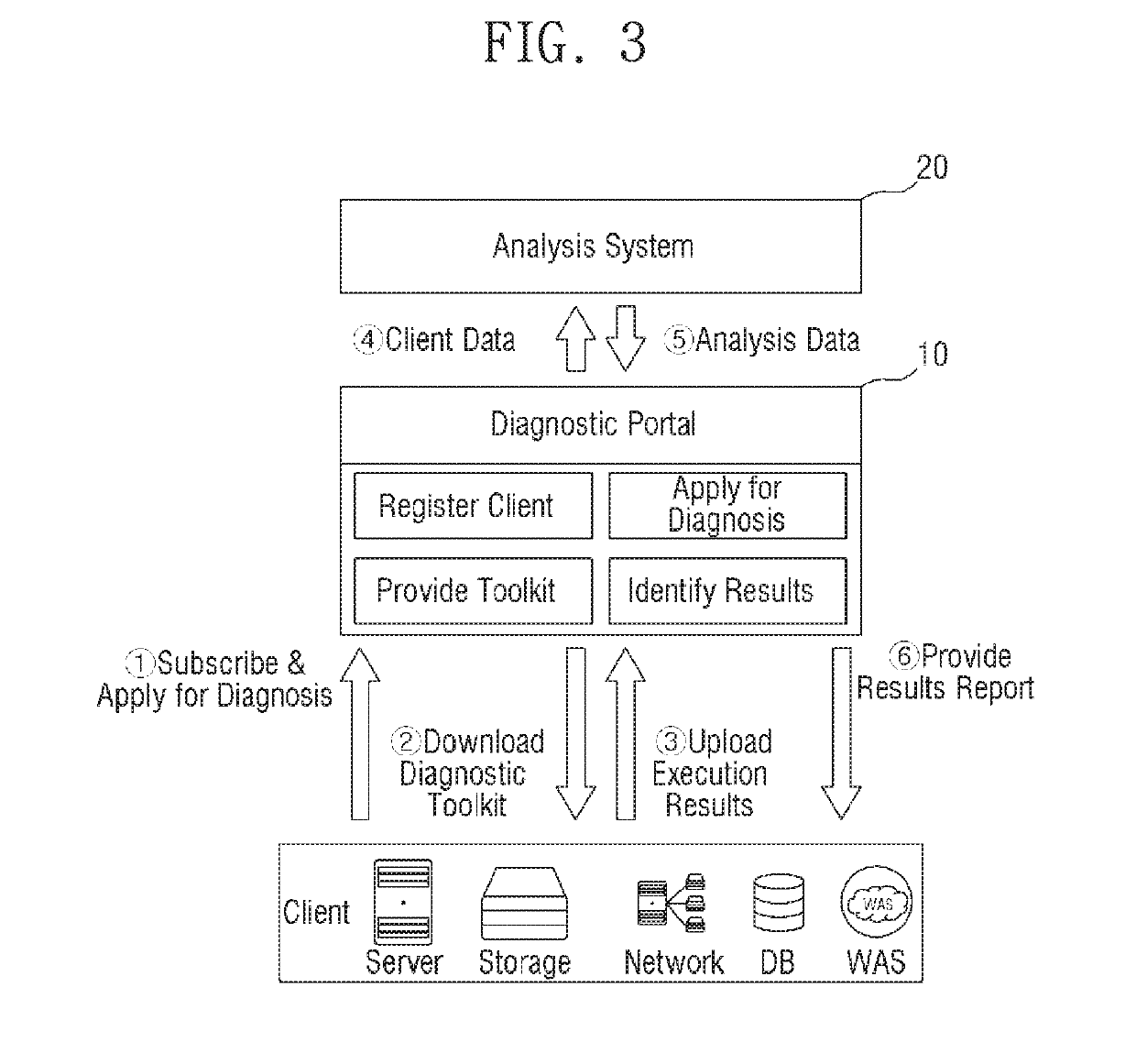
A system for diagnosing and analyzing infrastructure, comprising: a storage unit storing a diagnostic script, which is for collecting system information from a target system or at least one target operating server of the target system; a script transmission unit transmitting the diagnostic script to the target system to diagnose the target system; a system information collection unit receiving the system information from the target system or the at least one target operating server as a result of the running of the diagnostic script; an analysis engine storage unit storing at least one analysis rule corresponding to the target system or the at least one target operating server; and an analysis information generation unit analyzing the system information by using the analysis rule, and generating analysis information regarding the target system and the at least one target operating server based on the results of the analyzing.

Description

[0001]This application claims priority to Korean Patent Application No. 10-2016-0150476, filed on Nov. 11, 2016, and all the benefits accruing therefrom under 35 U.S.C. § 119, the disclosure of which is incorporated herein by reference in its entirety.BACKGROUND1. Field[0002]The present disclosure relates to an infrastructure diagnostic system and method, and more particularly, to a method and system for diagnosing information technology (IT) infrastructure such as a web server, a web application server (WAS), and a database (DB) server, providing a results report based on the results of the diagnosis, and providing a customized guide capable of addressing any vulnerabilities found by the diagnosis.2. Description of the Related Art[0003]Most small- to medium-size companies have their own information technology (IT) infrastructure for their business, such as, for example, servers for operating groupware or homepage servers for providing product information and manual files to general...

Claims


Application Information

Patent Timeline
Patent Type & Authority Patents(United States)
IPC IPC(8): G06F21/57H04L29/06G06Q30/04
CPCH04L63/1433G06Q30/04G06F21/577G06F2221/034G06Q10/063G06Q10/0637G06Q10/10G06Q50/10
Inventor HAN, IN CHULMAENG, SEUNG YOULCHOI, SUNG HWANSUNG, MIN HOLEE, JI YUNPYUN, DO SANSEO, YOUNG BEOMSONG, SEONG DAEKIM, EUN YOUNGHONG, SUNG SOONCHOI, JEONG AKWON, YOO MIPARK, CHANG WONKIM, MUN HWAN
Owner SAMSUNG SDS CO LTD
Learn More