Electropneumatic Position Regulator

a technology of electro-pneumatic position and regulator, which is applied in the direction of fluid couplings, clutches, couplings, etc., can solve the problems of pressure increase within the housing, and achieve the effect of increasing functional safety

Inactive Publication Date: 2014-03-06
SIEMENS AG
View PDF12 Cites 5 Cited by
  • Summary
  • Abstract
  • Description
  • Claims
  • Application Information

AI Technical Summary

Benefits of technology

[0009]It is the object of the invention to provide an electropneumatic position regulator which has increased functional safety.

Problems solved by technology

If the valves are accommodated in a gas-tight housing, this leads to a pressure increase within the housing.

Method used


Image

  • Electropneumatic Position Regulator
  • Electropneumatic Position Regulator

Examples


Embodiment Construction

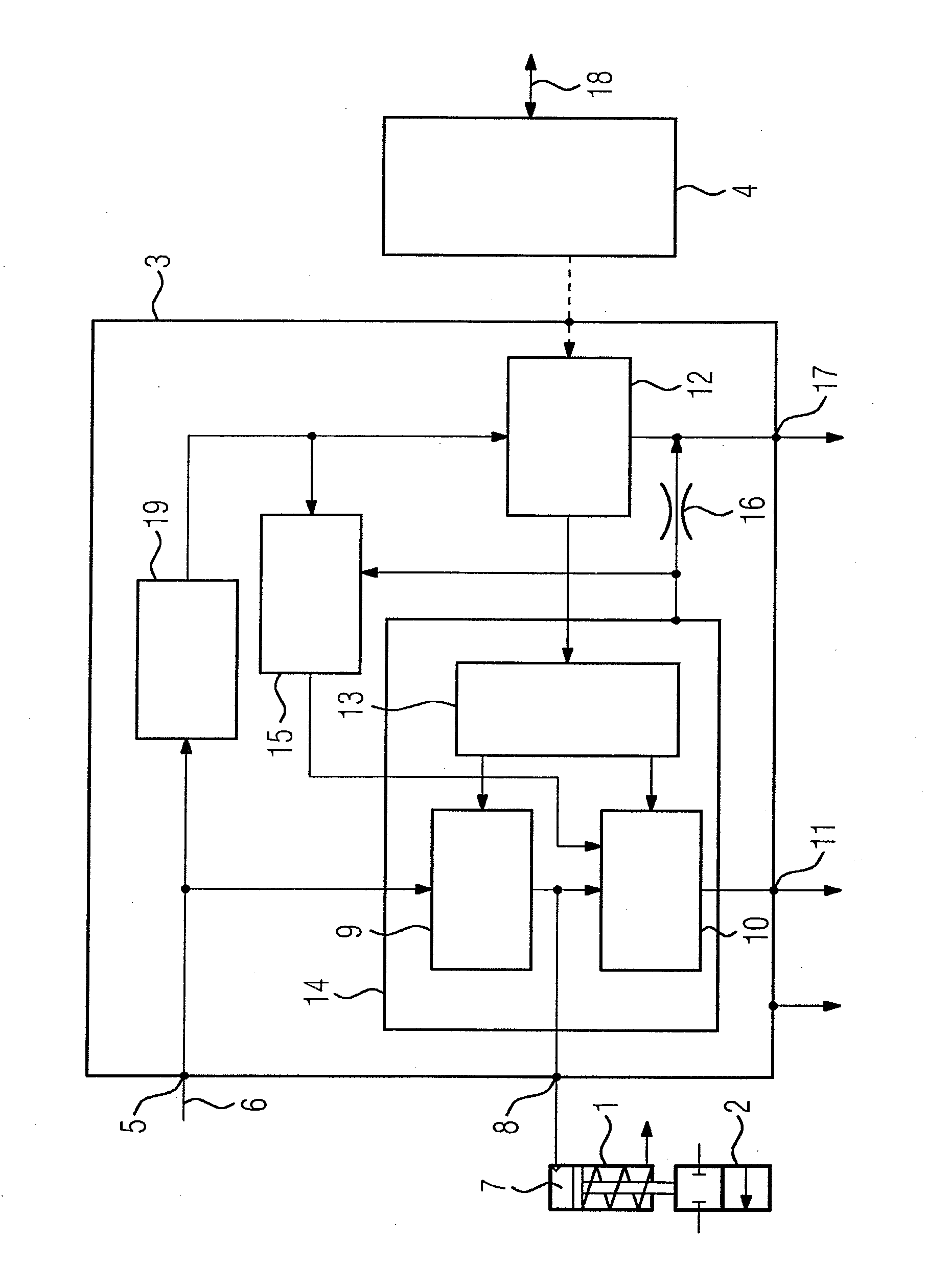
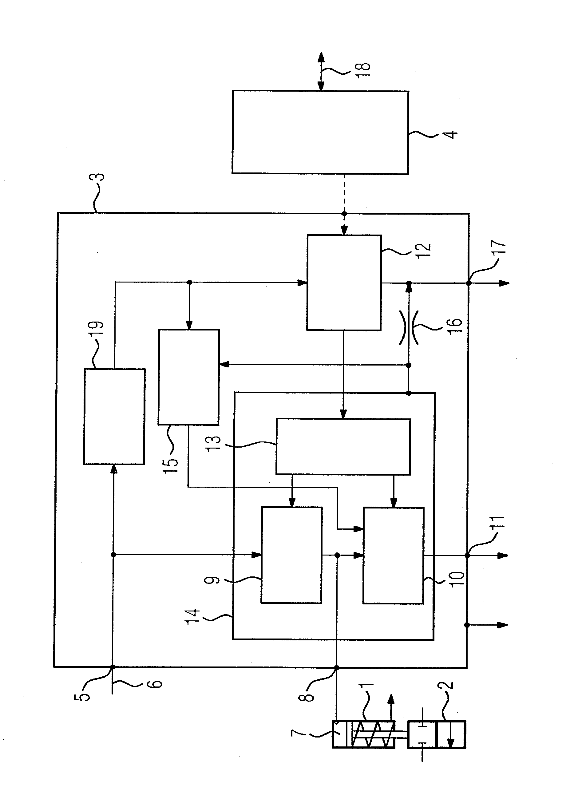
[0020]The FIGURE shows only those parts of an electropneumatic position regulator that contribute to the understanding of the invention, and also shows a pneumatic drive 1, connected to the electropneumatic position regulator, for a servo unit 2, in this case a process valve. The pneumatic position regulator has a pilot-control valve 3 and regulator electronics 4. A feed air port 5 serves for connection of a compressed-air supply line 6 via which, for example, compressed air is supplied at 6 bar pressure to the pilot-control valve 3. The upper chamber 7 of the drive 1 is connected to an exit air port 8 of the pilot-control valve. Depending on actuation, it is either the case that compressed air is conducted from the compressed-air supply line 6 to the chamber 7 by a feed air valve 9, or the compressed air is discharged from the pressure chamber 7 via a valve outlet 11 into the environment by an exit air valve 10. By means of a suitable locking mechanism which, for clarity, is not il...


PUM


Abstract

The invention relates to an electropneumatic position controller having a controllable valve group (9, 10, 13) arranged in the position controller and having at least one valve (9, 10), by means of which in normal operation either compressed air supplied by means of a compressed air supply line (6) can be fed to an exhaust connection (8) or air fed by means of the exhaust connection (8) can be discharged to the outside, depending on the actuation of the valve group. In order for the valve group to be brought in a safe position, even in the event of a leak in one of the components thereof, said group is arranged in a gas-tight housing (14) within the position controller and means (15) are provided for monitoring the pressure in the housing (14) and for actuating the valve group (9, 10, 13) such that if the pressure in the housing (14) exceeds a predefined threshold value, said group is brought in the predefined safe position.

Description

CROSS-REFERENCE TO RELATED APPLICATIONS[0001]This is a U.S. national stage of application No. PCT / EP2012 / 056498 filed 11 Apr. 2012. Priority is claimed on German Application No. 10 2011 007 629.8 filed 18 Apr. 2011, the content of which is incorporated herein by reference in its entirety.BACKGROUND OF THE INVENTION[0002]1. Field of the Invention[0003]The invention relates to an electropneumatic position regulator having a feed air port for connection to a compressed-air supply line, at least one exit air port for connection to a pneumatic drive of a servo unit, and a controllable valve group arranged in the electropneumatic position regulator.[0004]2. Description of the Related Art[0005]For the control of process valves, use is commonly made of pneumatic servo drives as servo units, in which a diaphragm that acts on a servo element, such as a lifting rod connected to a closing body, is acted on with a variable pressure, for the purpose of generating movements, via a gaseous medium t...

Claims


Application Information

Patent Timeline
Patent Type & Authority Applications(United States)
IPC IPC(8): F15B20/00F15B19/00
CPCF15B19/005F15B20/005F15B2211/30575F15B2211/6306F15B2211/87F15B2211/8752F15B2211/8855
Inventor MEINHOF, ANDRE-HEINRICH
Owner SIEMENS AG
Why Eureka
Try Eureka