Method, apparatus and system for controlling swirl of exhaust in a gas turbine

Inactive Publication Date: 2014-03-06
GENERAL ELECTRIC CO
View PDF5 Cites 9 Cited by
  • Summary
  • Abstract
  • Description
  • Claims
  • Application Information

AI Technical Summary

Benefits of technology

[0005]An aspect of the present invention relates to a strut of an exhaust diffuser of a gas turbine. The strut can comprise a foil part, one or more shape memory devices attached to the foil part, and one or more memory device heaters. Each shape memory device

Problems solved by technology

Change in swirl of gas turbine exhaust gases at off-design/part load conditions is a key driver of exhaust diffuser inefficiency that adversely impacts gas turbine perf

Method used


Image

  • Method, apparatus and system for controlling swirl of exhaust in a gas turbine
  • Method, apparatus and system for controlling swirl of exhaust in a gas turbine
  • Method, apparatus and system for controlling swirl of exhaust in a gas turbine

Examples


Embodiment Construction

[0016]Novel method, system, and apparatus for controlling swirl of exhaust gas in a gas turbine are described. In one aspect, the described method, system, and apparatus utilize memory materials to control the flow area of the exhaust gas, the swirl angle of the exhaust gas, or both based on the load on the gas turbine.

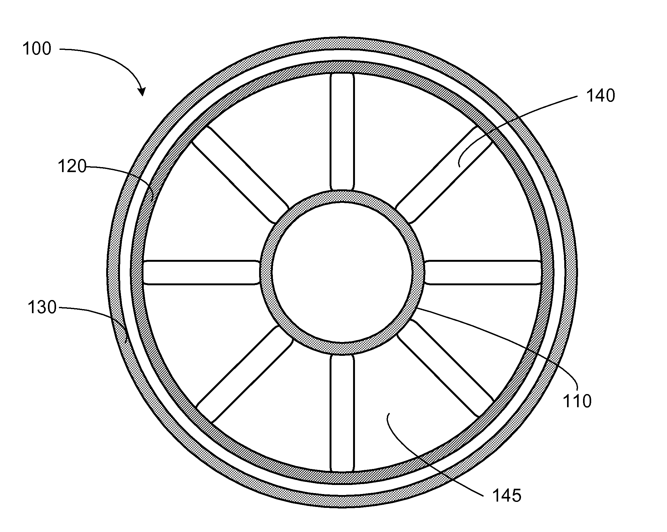
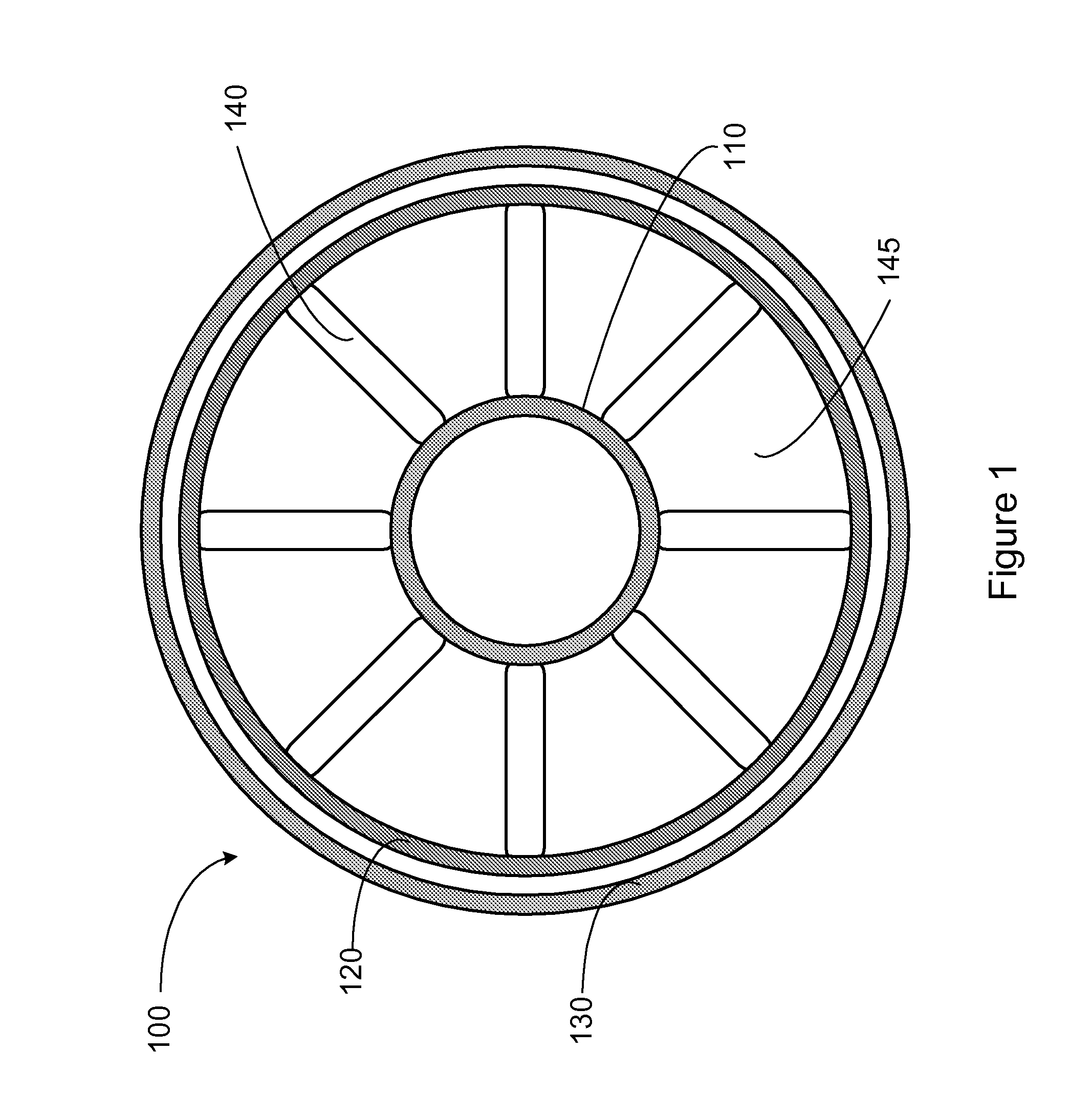
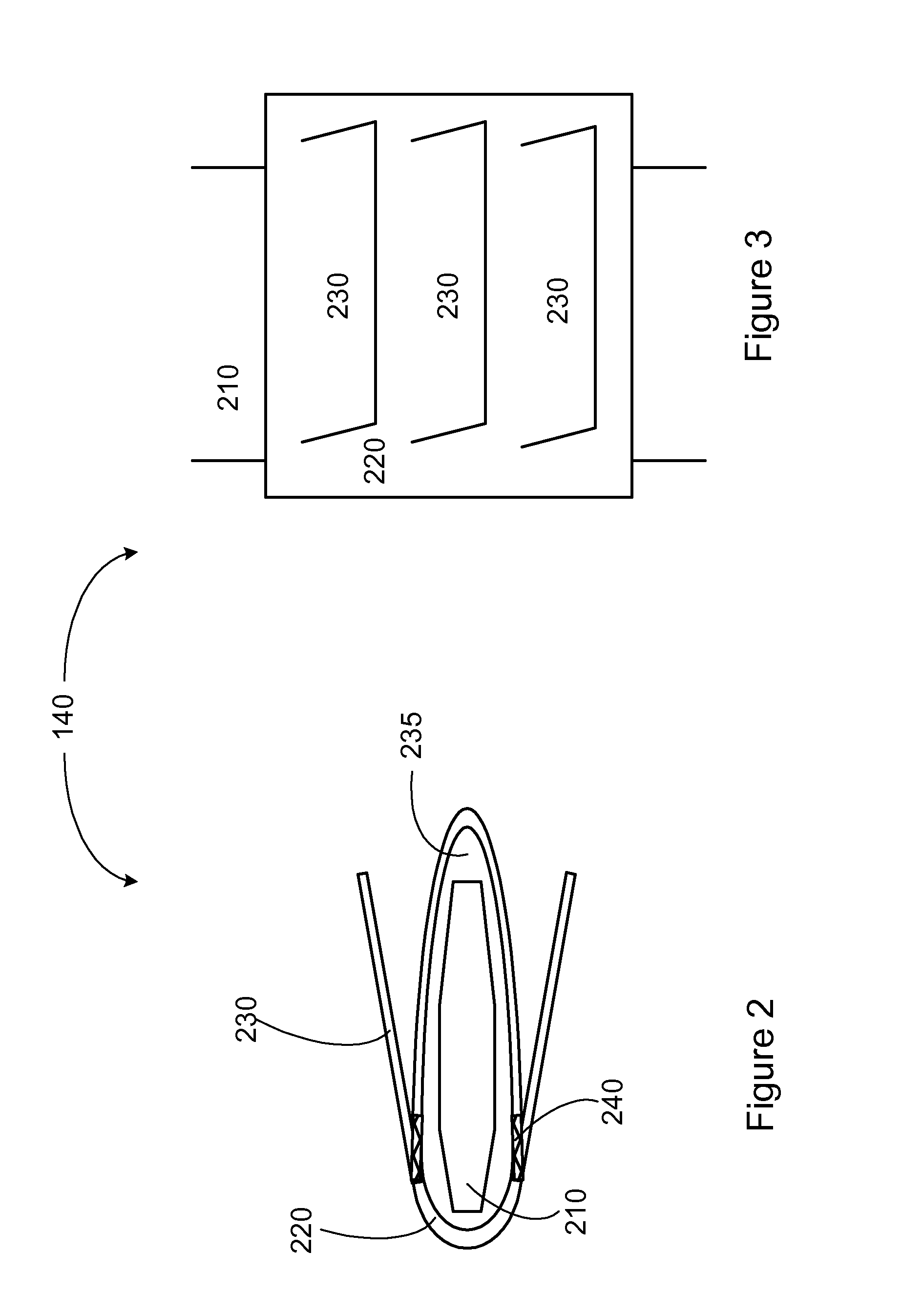
[0017]FIG. 1 illustrates a front view of an example exhaust diffuser embodiment of a gas turbine according to the present invention. As seen the example exhaust diffuser 100 can include a shroud 110 and a wall 120 that surrounds the shroud 110. The exhaust diffuser 100 may be double walled. In this instance, the exhaust diffuser 100 may also comprise an outer wall 130 that surrounds the wall 120, which may also be referred to as the inner wall 120. The exhaust diffuser 100 can include a plurality of struts 140. Each strut 140 can extend from the shroud 110 to the wall 120. A plurality of exhaust flow passages 145 can be defined. Each flow passage 145 can be bounded by...


PUM


Abstract

Change in swirl of gas turbine exhaust gases at off-design conditions is a key driver of exhaust diffuser inefficiency that adversely impact the gas turbine performance. Conventional ways to control swirl such as blowing, suction, and vortex generation are undesirable since they require parasitic power, are complex to design, and dilute the exhaust gas energy. To address such short comings, shape memory devices are incorporated into struts of an exhaust diffuser of a gas turbine. The shape memory devices change shape in accordance with heat, which can be applied through memory device heaters. By controlling the memory device heaters, the heat applied to the shape memory devices can be controlled. The shapes of the struts can be altered through altering the shapes of the memory device in consideration of load conditions to increase the efficiency.

Description

[0001]One or more aspects of the present invention relate to method, apparatus and system for controlling swirl of exhaust in a gas turbine. In particular, one or more aspects relate to improving gas turbine part load performance.BACKGROUND OF THE INVENTION[0002]A typical gas turbine system includes a compressor, one or more combustors, and a turbine at the rear. The compressor compresses ambient air. The compressed air exits the compressor and flows to the combustors where it mixes with fuel and ignites to generate combustion gases having high temperature and pressure. The high energy gas exits the combustors and flow to the gas turbine where they expand to produce work. An exhaust diffuser downstream of the turbine converts the kinetic energy of the exhaust gas flow exiting the turbine into potential energy in the form of increased static pressure. The exhaust diffuser typically includes struts that support the bearing.[0003]Change in swirl of gas turbine exhaust gases at off-desi...

Claims


Application Information

Patent Timeline
IPC IPC(8): F02C7/00F03G7/06
CPCF01D17/10F01D25/30F01D9/02F05D2300/505F01D25/246
Inventor SUBBAREDDYAR, THANGARAJMUTHURAMALINGAM, MAHENDHRACHILHATEY, NACHIKET
Owner GENERAL ELECTRIC CO
Why Eureka
Try Eureka