Active vortex generator based on electromagnetic excitation

A vortex generator and electromagnetic vibration exciter technology, applied in the direction of fluid flow, vortex generation, drag reduction, etc., can solve the problems of limited flow control effect and weak local flow disturbance, and achieve good flow control effect and high adjustment freedom. degree of effect

Inactive Publication Date: 2014-05-28
SHANGHAI JIAO TONG UNIV
View PDF6 Cites 8 Cited by
  • Summary
  • Abstract
  • Description
  • Claims
  • Application Information

AI Technical Summary

Problems solved by technology

However, the displacement generated by the piezoelectric device in the prior art is small, and the local flow disturbance generated by it is weak...

Method used


Image

  • Active vortex generator based on electromagnetic excitation
  • Active vortex generator based on electromagnetic excitation
  • Active vortex generator based on electromagnetic excitation

Examples


Embodiment 1

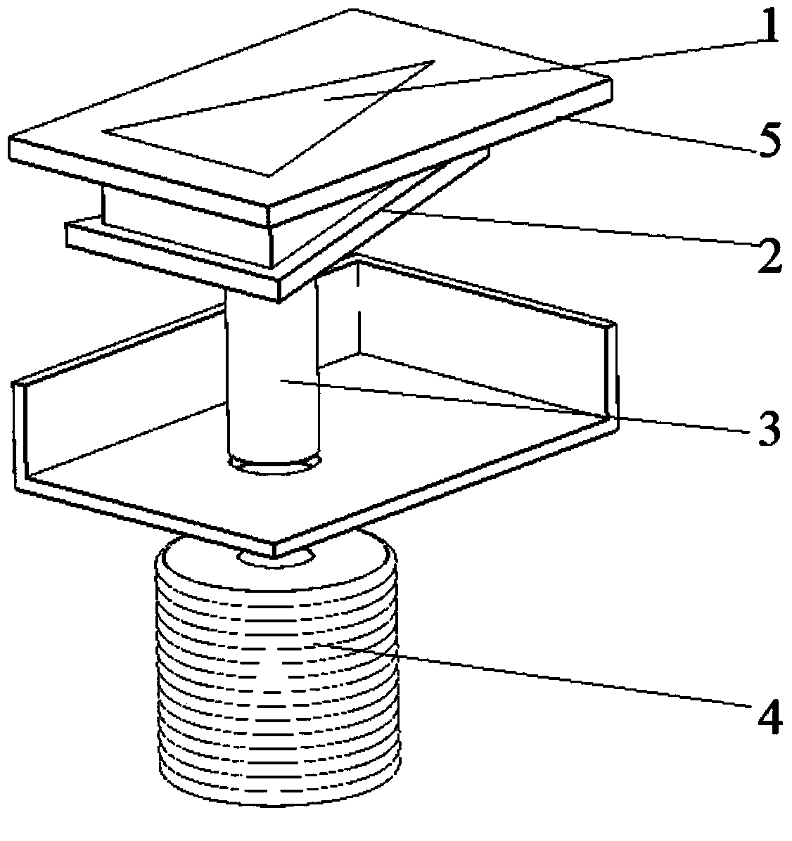
[0019] Such as figure 1 As shown, the present embodiment includes: a vibrating plate 1, a frame structure 2, a permanent magnet 3 and an electromagnetic exciter 4, wherein: the aircraft skin 5 is provided with a groove structure adapted to the cross-sectional shape of the vibrating plate 1, and the vibrating plate 1 is embedded in the groove structure, and its lower surface is provided with a frame structure 2 with a cross-sectional shape larger than the groove structure to prevent the vibrating piece 1 from falling off, and the bottom is fixedly connected with the permanent magnet 3. The horizontal plane of the aircraft skin 5 remains consistent, the electromagnetic exciter 4 is arranged below the permanent magnet 3, and a gap is provided between the two so that the vibrating piece 1 vibrates vertically;

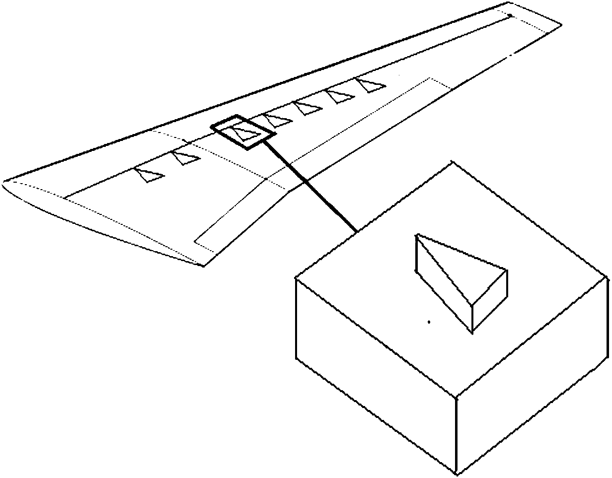
[0020] Such as figure 2 As shown, the position of the vibrating plate 1 is located on the surface of the wing of the aircraft to control the stall of the wing and achieve...

Embodiment 2

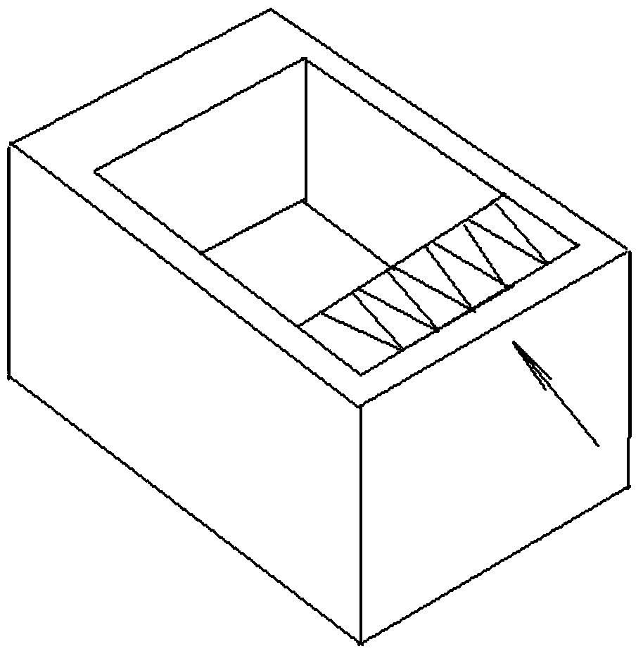
[0028] The structure of this embodiment is the same as that of Embodiment 1, and the position of the vibrating piece 1 is as follows image 3 As shown, the position of the vibrating plate 1 is located in the leading edge cavity of the aircraft, which is for cavity noise control and achieves the effect of reducing noise. The arrow in the diagram indicates the direction of incoming flow.

[0029] The pilot manually or the avionics system automatically adjusts the voltage signal applied to the vibrating plate 1, which can control the position of the vibrating plate 1 to produce four states: maintain a flat state, protrude and maintain a stable state, a fixed frequency stretching vibration state, and a random frequency stretching vibration The first state is suitable for noise-free control; the latter three states are suitable for noise control, which can interfere with the turbulent flow of the shear layer inside the cavity, generate flow vortices, and suppress the shear layer and...


PUM


Abstract

The invention belongs to the technical field of aerodynamics, and discloses an active vortex generator based on electromagnetic excitation. The active vortex generator based on electromagnetic excitation comprises a vibrating reed, a frame structure, a permanent magnet and an electromagnetic exciter, wherein the vibrating reed, the frame structure, the permanent magnet and the electromagnetic exciter are sequentially arranged in a wing of an aircraft or a leading-edge cavity of the aircraft from top to bottom. When the active vortex generator is arranged in the wing of the aircraft, a groove structure which is matched with the vibrating reed in cross-section shape is arranged on the skin of the aircraft, the vibrating reed is embedded into the groove structure, and when the vibrating reed is buried inside the skin of the aircraft, the upper surface of the vibrating reed and the horizontal plane of the skin of the aircraft are kept consistent. According to the active vortex generator based on electromagnetic excitation, active adjustment of flow control is achieved, the parasitic drag and adverse influence of the active vortex generator under the off-design working conditions are reduced, and the purposes of optimal drag reduction and optimal noise reduction are achieved.

Description

technical field [0001] The invention relates to a device in the technical field of aerodynamics, in particular to an active vortex generator based on electromagnetic excitation. Background technique [0002] Vortex generators have extensive engineering value in suppressing flow separation and reducing noise. For example, when an aircraft is flying at a high angle of attack, airflow separation often occurs on the surface of the aircraft body, resulting in greater aerodynamic drag and causing control instability problems. The vortex generator can form a flow direction vortex structure in its wake flow. The vortex structure entrains the high-energy fluid to interact with the low-energy fluid in the downstream boundary layer. Through energy transfer, the high-energy fluid can effectively overcome the reverse in the separation flow. Pressure gradient, and then to achieve the purpose of inhibiting or eliminating flow separation, to achieve the effect of reducing aerodynamic resis...

Claims


Application Information

Patent Timeline
IPC IPC(8): F15D1/00B64C23/06
CPCY02T50/10
Inventor 李伟鹏李子佳
Owner SHANGHAI JIAO TONG UNIV
Why Eureka
Try Eureka