Multiple point overboard extractor for gas turbine

a gas turbine and extractor technology, applied in the field of gas turbine systems, can solve problems such as detrimental effects and insufficient cooling of combustor hardwar

Inactive Publication Date: 2014-03-06
GENERAL ELECTRIC CO
View PDF2 Cites 41 Cited by
  • Summary
  • Abstract
  • Description
  • Claims
  • Application Information

AI Technical Summary

Problems solved by technology

However, if the overboard extraction is not carefully controlled, it can have detrimental effects.
For example, the combustor hardware may not be adequately cooled.

Method used


Image

  • Multiple point overboard extractor for gas turbine
  • Multiple point overboard extractor for gas turbine
  • Multiple point overboard extractor for gas turbine

Examples


Embodiment Construction

[0019]One or more aspects of a novel multiple point overboard extractor, a gas turbine system incorporating the multiple point overboard extractor and a method for overboard extraction are described. Among many advantages, the inventive aspects enable operability, emissions, and durability benefits in using the gas turbine system.

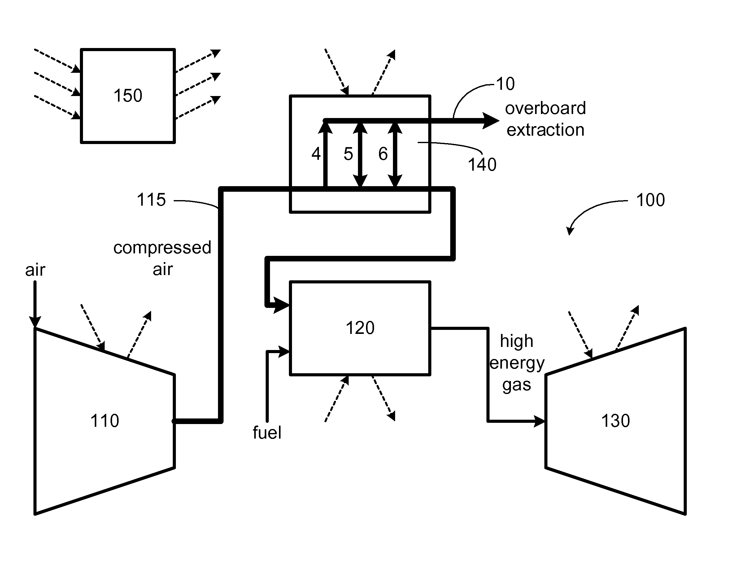
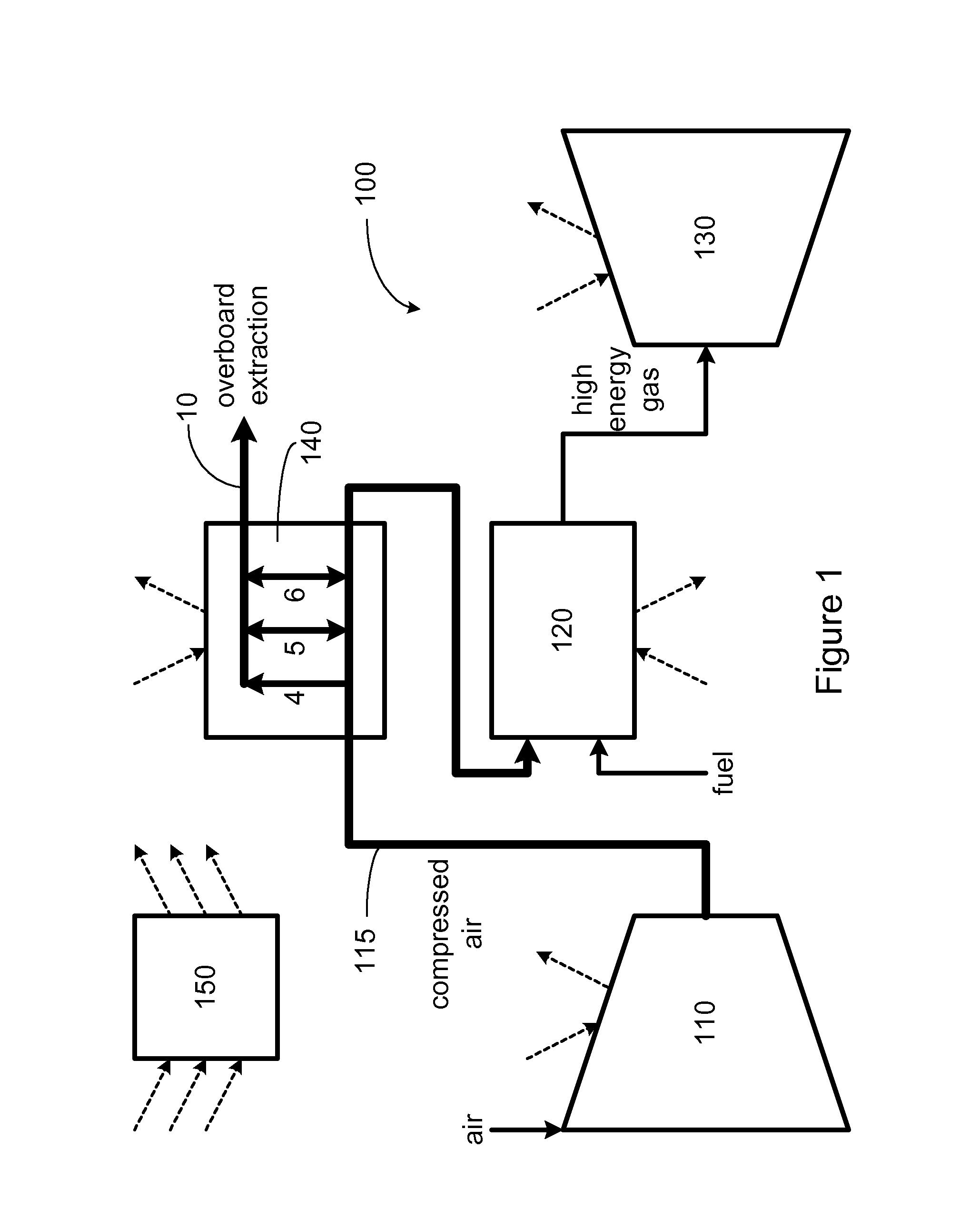
[0020]FIG. 1 illustrates a gas turbine system 100 according to an embodiment of the present invention. The example gas turbine system 100 includes a compressor 110, a combustor 120, a turbine or an expander 130, an overboard extractor 140, and a controller 150. The compressor 100 is arranged to compress fluid such as air. The compressed fluid is provided to the combustor 120 via a compressed fluid path 115. In this embodiment, the compressed fluid path 115 is fluid path from an exit of the compressor 110 to a head end 11 (see FIG. 2) of the combustor 120.

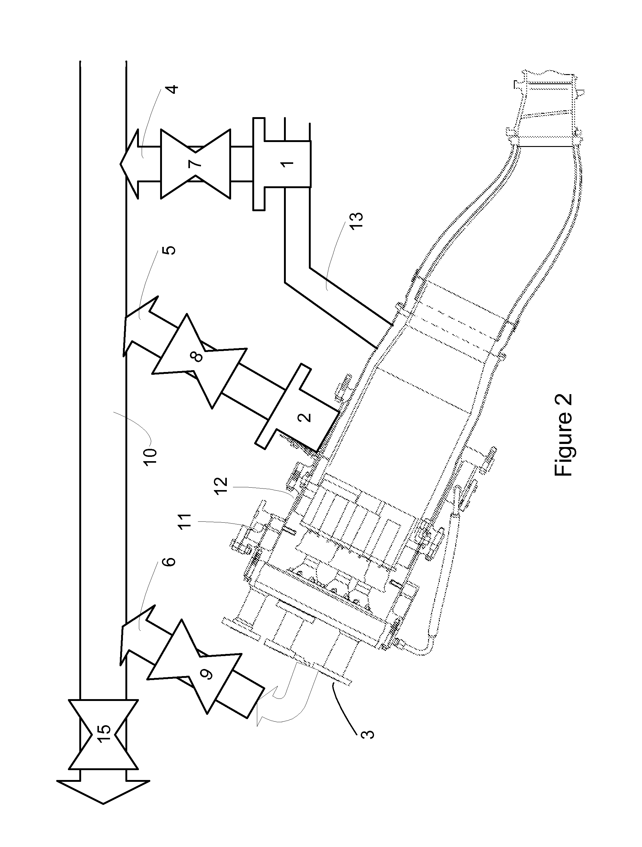
[0021]Note that in an example gas turbine system 100, the compressed fluid flows in a “flow sleeve” that...


PUM


Abstract

The disclosed overboard extractor provides overboard extraction of compressor fluid at multiple extraction points. The overboard extractor includes multiple extraction manifolds and a delivery manifold for extracting the compressor fluid from the multiple extraction points. The overboard extractor also includes extraction valves and a delivery valve to control the extraction flow through each extraction manifold. The overboard extractor can operate in a delivery mode, a closed loop mode, or a mixed mode.

Description

[0001]One or more aspects of the present invention relate to multiple point overboard extractor for a gas turbine. In particular, one or more aspects of the present invention relate to overboard extraction of compressed fluid through the multiple extraction points.BACKGROUND OF THE INVENTION[0002]In a typical gas turbine system, air is compressed by a compressor and the compressed air is mixed with fuel for combustion. A gas turbine system can also include features to extract a portion of the compressed air fluid, e.g., compressed air, from the compressor to be diverted for purposes other than combustion. As an example, the diverted compressed air can be used to cool parts of the combustor hardware. In an airplane, the diverted compressed air can be used to pressurize the cabin.[0003]However, if the overboard extraction is not carefully controlled, it can have detrimental effects. For example, the combustor hardware may not be adequately cooled. Thus, it is desirable to manage the o...

Claims


Application Information

Patent Timeline
Patent Type & Authority Applications(United States)
IPC IPC(8): F02C6/08
CPCF02C6/08F02C7/14Y02T50/60
Inventor SLOBODYANSKIY, ILYA ALEKSANDROVICHKRAEMER, GILBERTWILLIAMSON, DAVIDGINESSIN, LEONIDCUMMINGS, EDWARD
Owner GENERAL ELECTRIC CO
Why Eureka
Try Eureka