Diaphragm and backing cushion shaping for increased membrane life

Inactive Publication Date: 2014-03-06
ITT MFG ENTERPRISES LLC
View PDF1 Cites 9 Cited by
  • Summary
  • Abstract
  • Description
  • Claims
  • Application Information

AI Technical Summary

Benefits of technology

[0033]In summary, the present invention increases the life expectancy of the diaphragm by reducing the surface stress incurred during mechanical cycling, particularly during exposure to destructive process such as steam and co

Problems solved by technology

Although the membrane material is chosen to be compliant to these mechanical cycles, it has limitations, especially when combined with certain process requirements, such a

Method used


Image

  • Diaphragm and backing cushion shaping for increased membrane life
  • Diaphragm and backing cushion shaping for increased membrane life
  • Diaphragm and backing cushion shaping for increased membrane life

Examples


Embodiment Construction

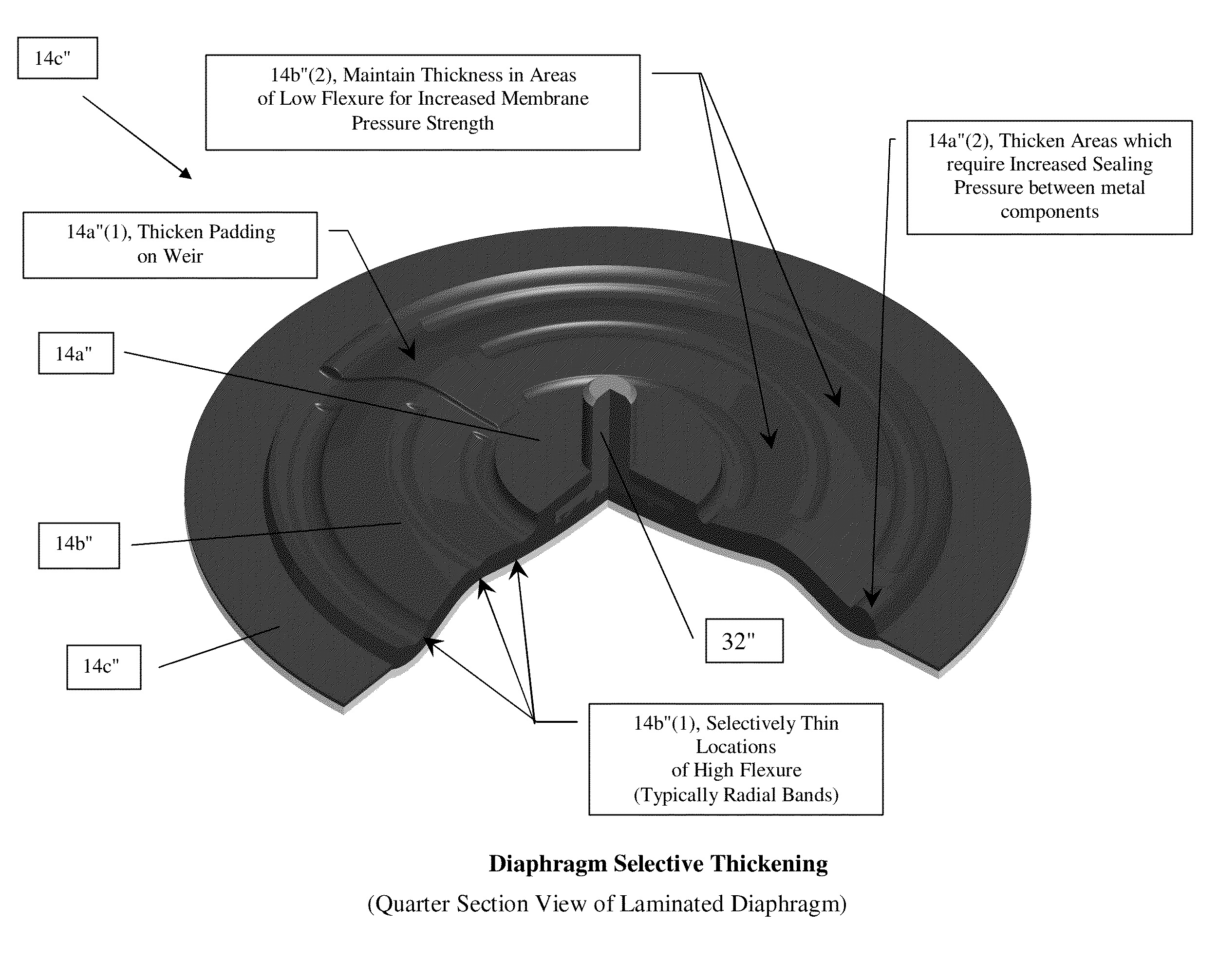
[0045]According to some embodiments, the present invention may take the form of apparatus, including a weir-type diaphragm valve generally indicated as 10, 10′ (e.g., see FIGS. 2a, 3a), that features a valve body 12 and a diaphragm 14, 14′. The valve body 12 may be configured with a fluid channel 12a and a weir 12b having a weir sealing portion 12c. The diaphragm 14, 14′ may be configured with two or more diaphragm portions or areas 14a, 14b, 14c (FIGS. 2a, 2b); 14a′, 14b′, 14c′ (FIGS. 3a, 3b); 14a″, 14b″, 14c″ (FIG. 4), including[0046]a diaphragm weir sealing portion 14a, 14a′, 14a″ at the weir 12b to respond to one force and travel against the weir sealing portion 12c to close the weir-type diaphragm valve 10 and stop fluid flow through the fluid channel 12a, and respond to a second force and travel away from the weir sealing portion 12c to open the weir-type diaphragm valve 10 and allow fluid flow through the fluid channel 12a,[0047]a center flexing portion 14b, 14b′, 14b″ off th...


PUM


Abstract

A weir-type diaphragm valve a valve body with a fluid channel and a weir having a weir sealing portion; and a diaphragm with two or more diaphragm portions, including a diaphragm weir sealing portion at the weir to respond to one force and travel against the weir sealing portion to close the weir-type diaphragm valve and stop fluid flow through the fluid channel, and respond to a second force and travel away from the weir sealing portion to open the weir-type diaphragm valve and allow fluid flow through the fluid channel, a center flexing portion off the weir configured to experience convex and concave flexing extremes when the weir-type diaphragm valve is closed and opened, and an outer sealing portion configured to be fully constrained between components, one of which includes the valve body, when the weir-type diaphragm valve is closed and opened. The diaphragm portions have different characteristics based on different material stresses associated with different functionality that each portion is configured to perform when the weir-type diaphragm valve is closed and opened.

Description

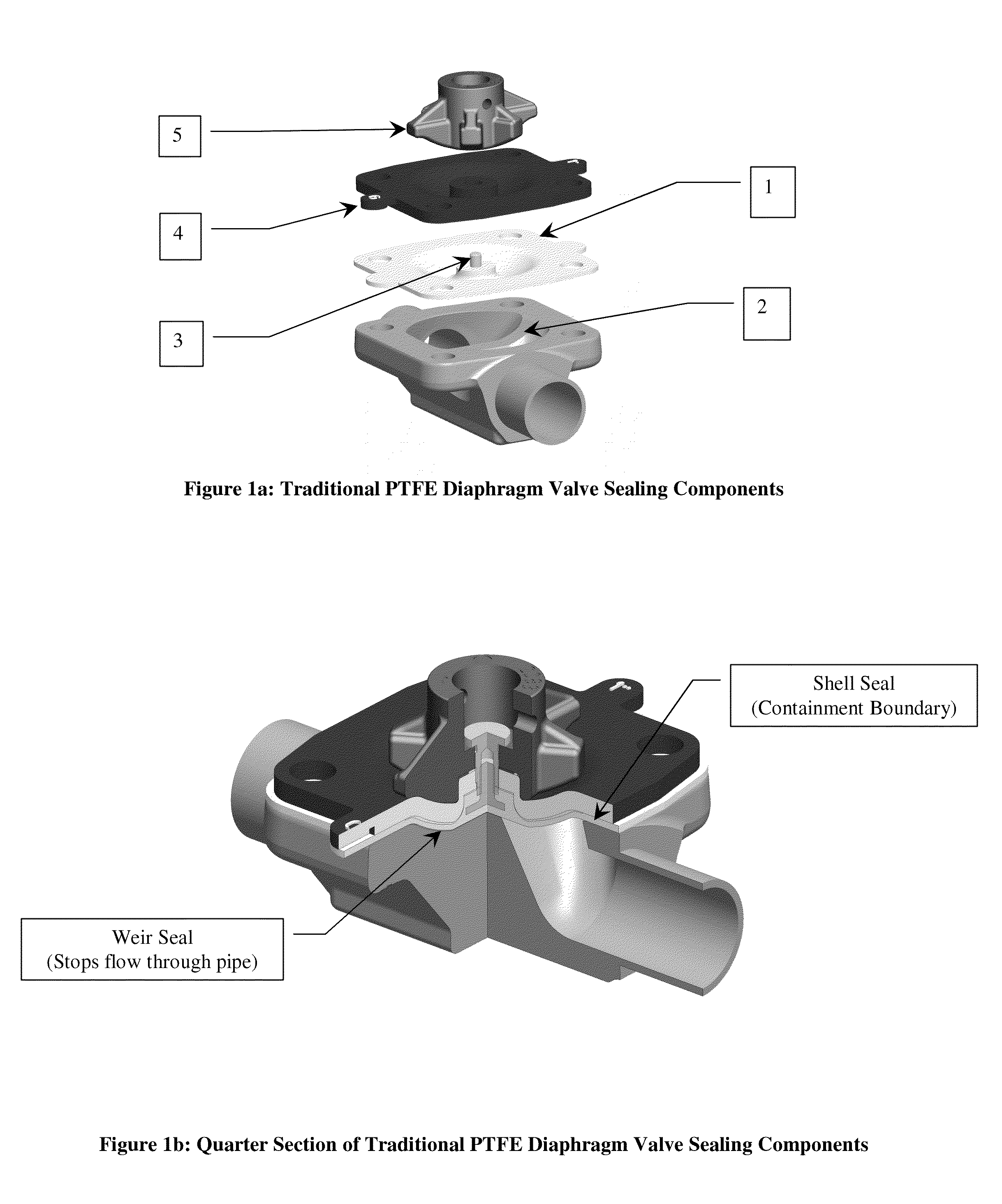
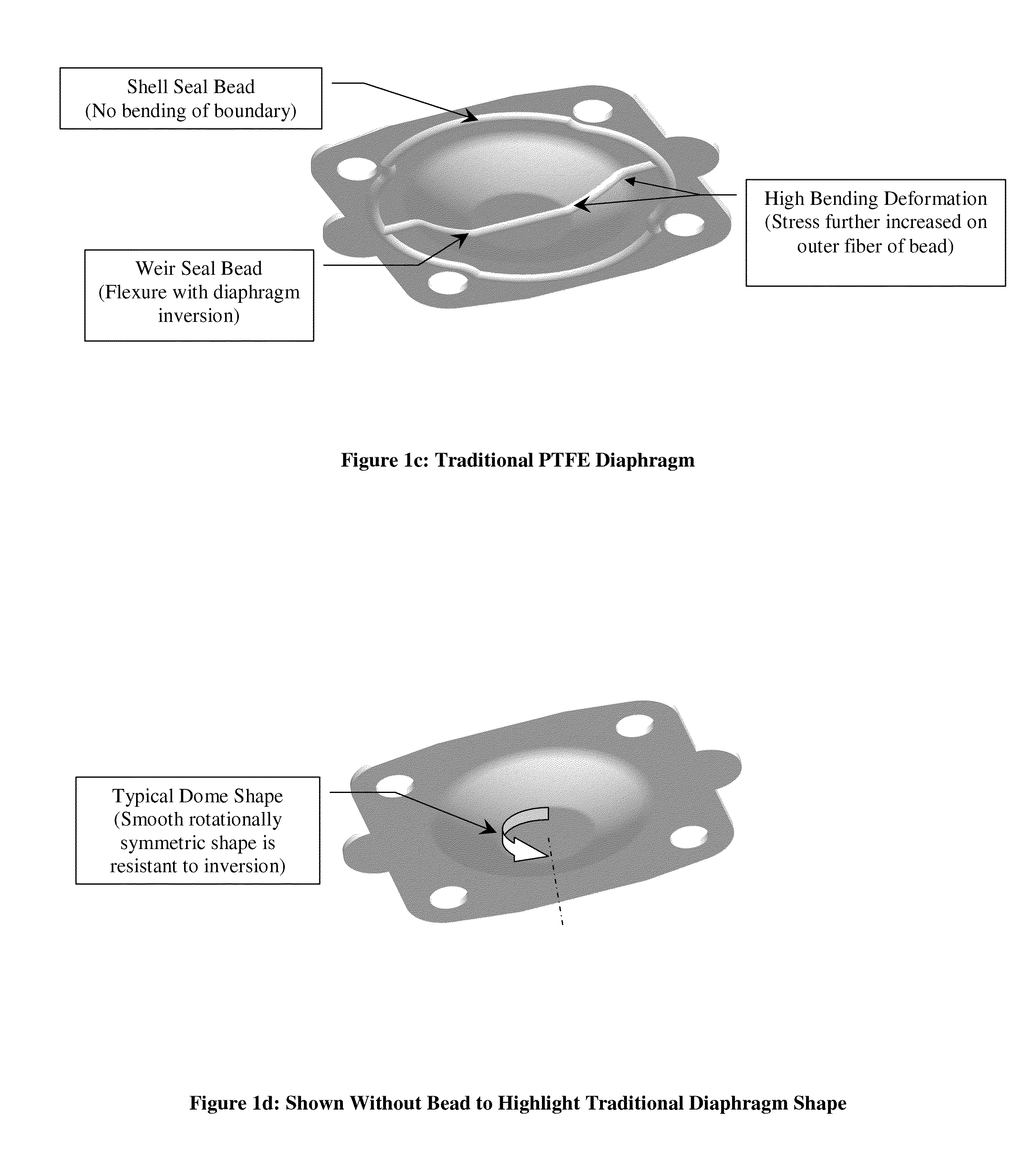
BACKGROUND OF THE INVENTION[0001]1. Field of the Invention[0002]The present invention relates to a diaphragm valve; and more particularly relates to a diaphragm valve having a weir.[0003]2. Brief Description of Related Art[0004]FIGS. 1a to 1d show different parts of a known weir-type diaphragm valve. In FIG. 1a, a diaphragm valve is sealed by a membrane, the diaphragm (1), which must repeatedly travel from a sealed position, against the body weir (2) to an open position. The diaphragm (1) is typically opened with a metal stud (3) embedded within the membrane. An outer seal of the diaphragm (1) is fully constrained while the center of the diaphragm (1) typically experiences the majority of travel to facilitate the open and closed positions. The shape cycles between convex and concave extremes for closed and open positions respectively. As a result, locations of greatest deformation, from bending magnitude and geometry such as thickness, result in the highest material stress. Although...

Claims


Application Information

Patent Timeline
IPC IPC(8): F16K7/12
CPCF16K7/126F16K7/16
Inventor MATALON, LOUIS E.
Owner ITT MFG ENTERPRISES LLC
Why Eureka
Try Eureka