Wireless Energy Transfer System

a wireless energy transfer and wireless technology, applied in the direction of transformers, transmission, inductances, etc., can solve the problems of battery power in a laptop or a cell phone when a recharging procedure is missed, the problem of providing power and communication functions to a highly distributed network of electronic devices without wired connection, and the problem of battery not being solved, so as to achieve the maximum variability of at least one capacitor

Active Publication Date: 2014-03-06
UNIVERSITY OF PITTSBURGH
View PDF6 Cites 43 Cited by
  • Summary
  • Abstract
  • Description
  • Claims
  • Application Information

AI Technical Summary

Benefits of technology

The patent describes a structural design for an LC resonant tank that includes a conductor coil and an insulator. The insulator is made up of an outer and inner cylindrical insulator that rotate relative to each other. The insulators form a capacitor that can be adjusted by rotating the insulators, which affects the capacitance of the tank. The conductor coil is a helical coil that connects to both insulators. The design provides maximum variability of the capacitor by extending the insulators along their respective cylinders. The technical effect is a more efficient and flexible LC resonant tank that can be easily adjusted for different applications.

Problems solved by technology

However, in many cases, these solutions are inadequate.
For example, running out of battery power in a laptop or a cell phone when a recharging procedure is missed is an unpleasant, but common event.
Currently, a surgical procedure is required to replace the entire device when its battery power is depleted.
One particular medical problem of high interest is the design of a wireless network of devices for the human body.
While the high significance of such a body network has been recognized by both the research community and industry, the problem of providing power and communication functions to a highly distributed network of electronic devices without wired connections and batteries has not been solved.

Method used


Image

  • Wireless Energy Transfer System
  • Wireless Energy Transfer System
  • Wireless Energy Transfer System

Examples


Embodiment Construction

[0051]Directional phrases used herein, such as, for example and without limitation, top, bottom, left, right, upper, lower, front, back, and derivatives thereof, relate to the orientation of the elements shown in the drawings and are not limiting upon the claims unless expressly recited therein.

[0052]As employed, herein, the statement that two or more parts or components are “coupled” together shall mean that the parts are joined or operate together either directly or through one or more intermediate parts or components.

[0053]As employed herein, the statement that two or more parts or components “engage” one another shall mean that the parts exert a force against one another either directly or through one or more intermediate parts or components.

[0054]As employed herein, the term “number” shall mean one or an integer greater than one (i.e., a plurality).

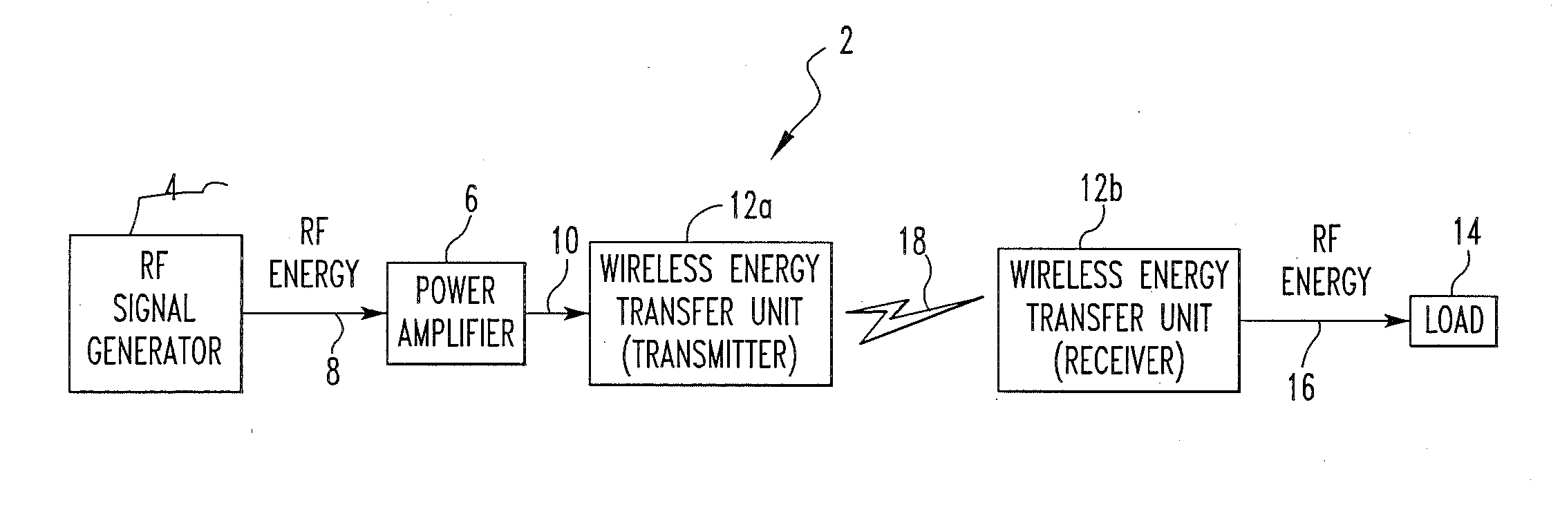
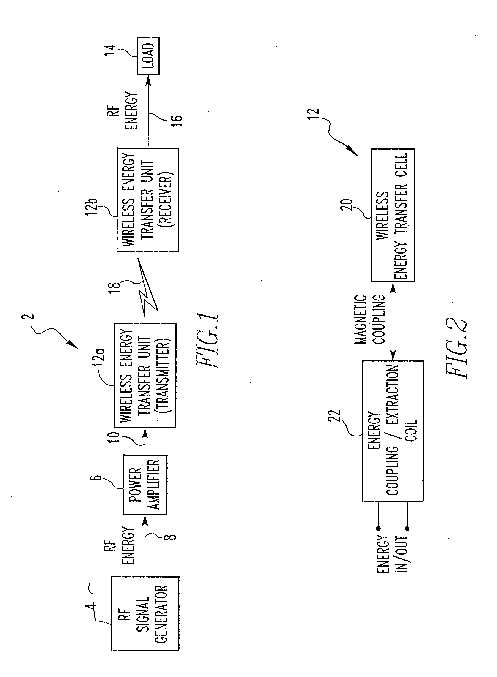
[0055]FIG. 1 is a block diagram of a wireless energy transfer system 2 according to one embodiment of the present invention. As des...


PUM

PropertyMeasurementUnit
operating frequencyaaaaaaaaaa
electrical energyaaaaaaaaaa
energyaaaaaaaaaa

Abstract

A wireless energy transfer system includes a first energy transfer unit having at least one resonant frequency, a second energy transfer unit having the at least one resonant frequency, and a load. The first wireless energy transfer unit includes a first coil magnetically coupled to a first wireless energy transfer cell, and the second wireless energy transfer unit includes a second coil magnetically coupled to a second wireless energy transfer cell. The first coil receives first energy and through the magnetic coupling between the first coil and the first wireless energy transfer cell, the first wireless energy transfer cell is caused to generate second energy, wherein the second wireless energy transfer cell receives the second energy and through the magnetic coupling between the second wireless energy transfer cell and the second coil, the second coil is caused to provide third electromagnetic wave energy to the load.

Description

CROSS-REFERENCE TO RELATED APPLICATION[0001]This application claims priority under 35 U.S.C. §119(e) from U.S. Provisional Application No. 61 / 096,466, entitled “Apparatus for Wireless Power and Data Transfer Over a Distance,” which was filed on Sep. 12, 2008, and U.S. Provisional Application No. 61 / 165,134, entitled “Wireless Energy Transfer System,” which was filed on Mar. 31, 2009, the disclosures of which are incorporated herein by reference.GOVERNMENT CONTRACT[0002]This work was supported in part by Army grant No. W81XWH05-C-0047. The United States government may have certain rights in the invention described herein.FIELD OF THE INVENTION[0003]The present invention relates to the transfer of energy wirelessly, and in particular to a wireless energy transfer system, and wireless energy transfer units and cells employed thereby, that allows energy, such as RF energy, to be transferred wirelessly using nonradiative resonant coupling for power transfer and / or data communications pur...

Claims


Application Information

Patent Timeline
Patent Type & Authority Applications(United States)
IPC IPC(8): H01F38/14
CPCH01F38/14H02J50/50H02J50/12H02J50/005H04B5/266H04B5/79
Inventor SUN, MINGUIHACKWORTH, STEVENSCLABASSI, ROBERTZHANG, FEILIU, XIAOYU
Owner UNIVERSITY OF PITTSBURGH
Why Eureka
Try Eureka