Thick film multilayer reflector with tailored layer thickness profile

a multi-layer reflector and thickness profile technology, applied in the field of reflective optical bodies, can solve the problems of affecting the application of certain applications, and can have deleterious consequences, and achieve the effect of substantial variability in reflection and transmission characteristics, and substantial effect on optical performan

Active Publication Date: 2008-06-10
3M INNOVATIVE PROPERTIES CO
View PDF31 Cites 10 Cited by
  • Summary
  • Abstract
  • Description
  • Claims
  • Application Information

AI Technical Summary

Benefits of technology

[0005]We have found that the layer thickness and the layer thickness profile of thick film multilayer reflectors can have a substantial effect on optical performance in the wavelength range of interest, such as the visible region. In effect, certain multilayer constructions that would be expected to provide smooth incoherent light reflection because of the relatively thick nature of the individual layers, have been found to produce substantial variability in reflection and transmission characteristics, even when averaging those characteristics using a suitable bandwidth smoothing filter. Such variability can have deleterious consequences in some applications.

Problems solved by technology

Such variability can have deleterious consequences in some applications.

Method used


Image

  • Thick film multilayer reflector with tailored layer thickness profile
  • Thick film multilayer reflector with tailored layer thickness profile
  • Thick film multilayer reflector with tailored layer thickness profile

Examples


Embodiment Construction

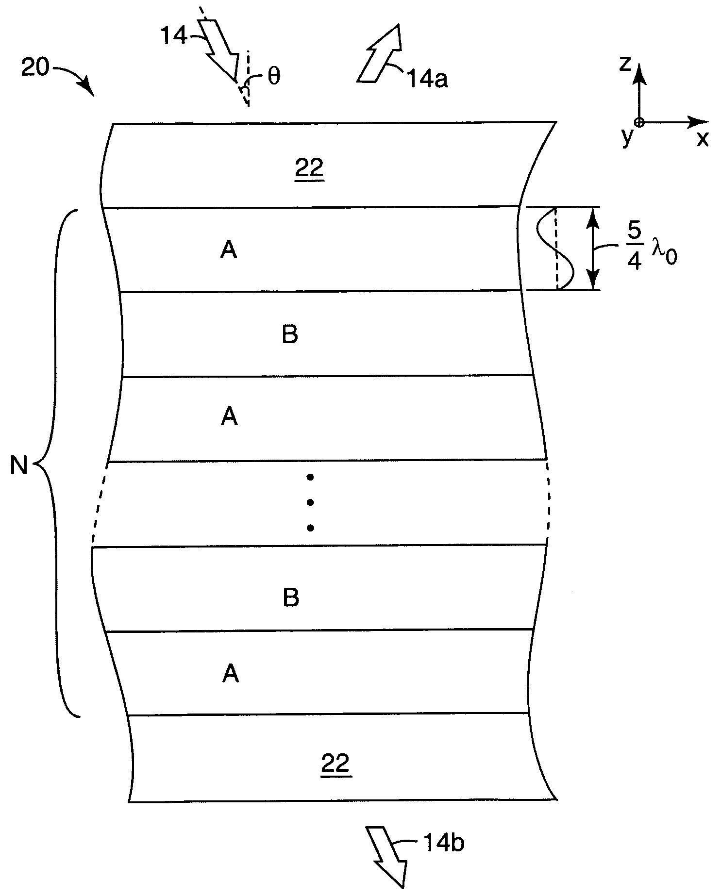
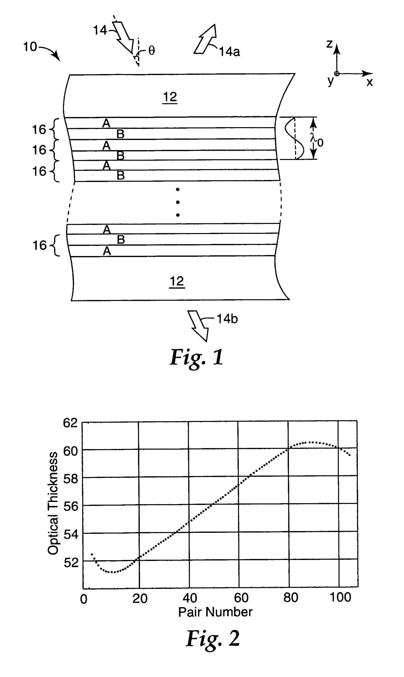
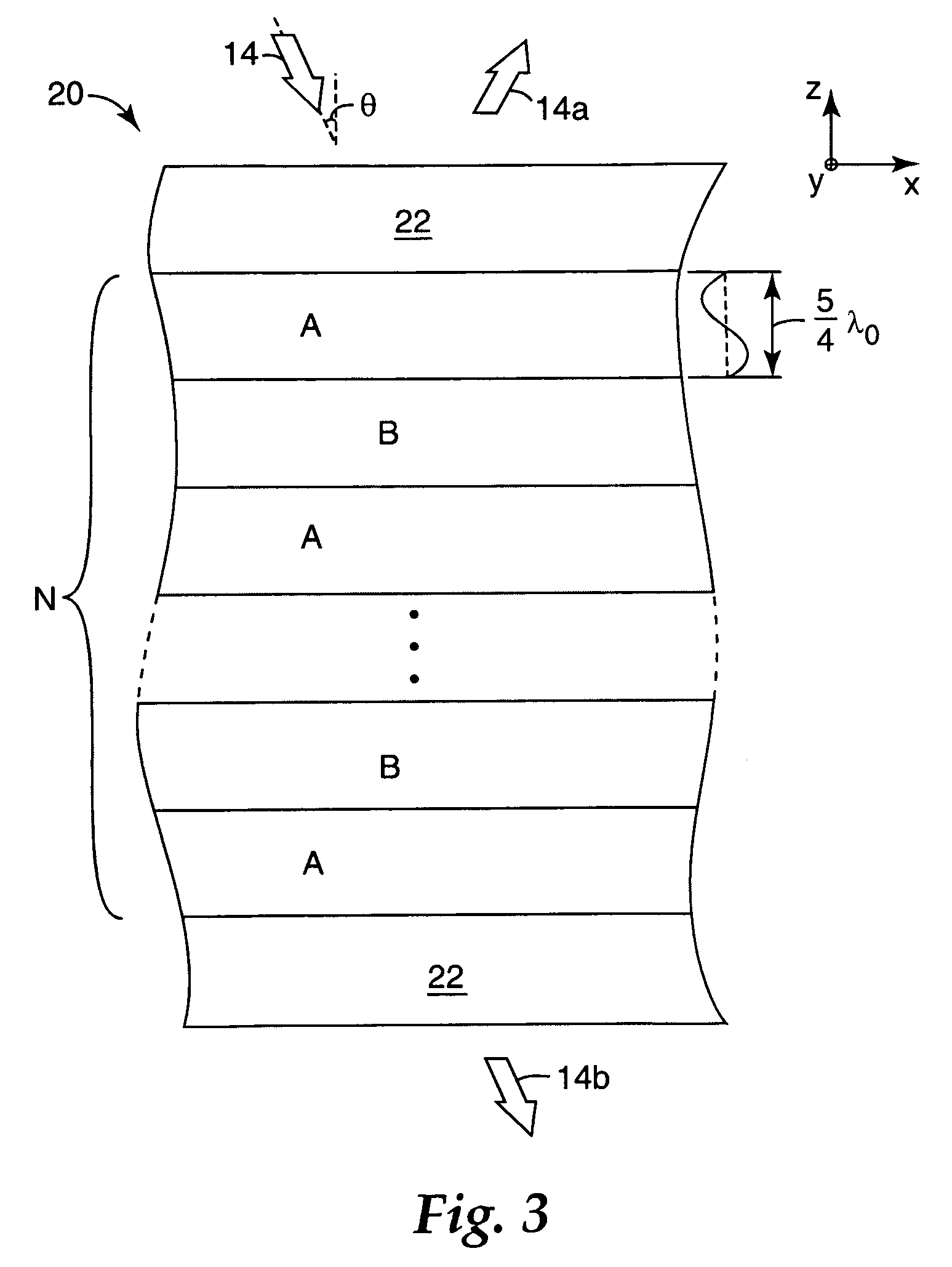
[0029]FIG. 1 shows a portion of a conventional thin film multilayer reflector 10. Reflector 10 is all polymeric and has a stack or packet of optically thin layers sandwiched between optically thick outer skin layers 12. The layer thicknesses shown in the figure are intended to be representative of optical thickness, as described below, rather than physical thickness. The reflector 10 is shown in relation to a Cartesian x-y-z coordinate system, with the z-axis corresponding to a thickness axis of the reflector and the x- and y-axes extending parallel to the plane of the layers and the interfaces between layers. Arrow 14 represents light incident on the film at an angle θ relative to the z-axis, with reflected light represented by arrow 14a and transmitted light by arrow 14b.

[0030]In the finished product, the optically thin layers are conventionally arranged in a repeating pattern along the z-axis of the reflector. The smallest unit of the repeating pattern is referred to as a unit c...


PUM


Abstract

A multilayer reflector useable to reflect or transmit light over the visible wavelength range includes optically thick constituent layers. The optical thickness of the constituent layers through the thickness of the reflector defines a layer thickness profile. The layers are arranged so that the thickness profile has a tailored non-uniform distribution, such as a graded distribution or a randomized distribution. The layers desirably have an optical thickness in a range from about one to five or one to ten design wavelengths. The reflector can be a polarizer, reflecting only one normally incident polarization state, or a mirror, reflecting two normally incident orthogonal polarization states.

Description

FIELD OF THE INVENTION[0001]The present invention relates to reflective optical bodies including but not limited to films, sheets, and plates, particularly those used in visible light applications such as liquid crystal display (LCD) devices and other electronic display devices, as well as to methods of making and using such optical bodies.BACKGROUND[0002]Thin film multilayer reflectors suitable for reflecting visible or near-visible light are known. Such reflectors have long been made by evaporating thin films of different inorganic dielectric light-transmissive materials in succession on a glass substrate in a vacuum chamber. The different refractive indices of adjacent layers form tens or hundreds of interfaces, each of which reflects light by Fresnel reflection, and coherent constructive or destructive interference of reflected light components provides the reflector with its reflection and transmission properties. It is also know to make thin film multilayer reflectors by an ex...

Claims


Application Information

Patent Timeline
Patent Type & Authority Patents(United States)
IPC IPC(8): G02B1/10B32B7/023G02B5/28G02B5/30G02B27/28
CPCB32B7/02G02B5/0816B32B7/023
Inventor NEVITT, TIMOTHY J.OUDERKIRK, ANDREW J.
Owner 3M INNOVATIVE PROPERTIES CO
Why Eureka
Try Eureka