Member-to-Member Fuse Connection

Active Publication Date: 2014-03-06
SIMPSON STRONG TIE
View PDF18 Cites 17 Cited by
  • Summary
  • Abstract
  • Description
  • Claims
  • Application Information

AI Technical Summary

Benefits of technology

[0017]In another embodiment, material, including, but not limited to elastomer, polymers and reinforced polymers, concrete or cementitious grout or other known materials

Problems solved by technology

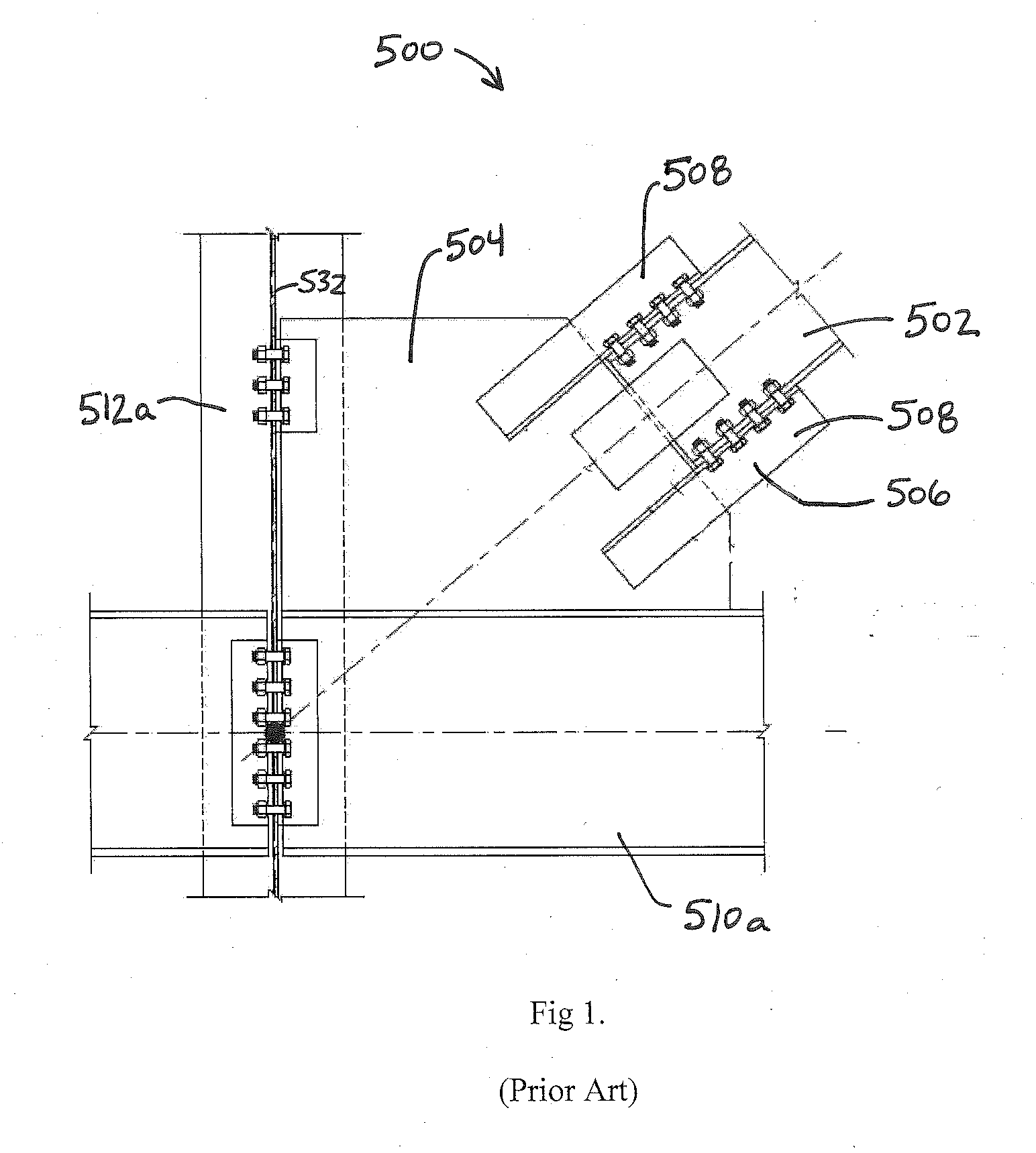
This type of connection has been used for many years, but is not typically implemented when seismic or other dynamic loading conditions require the connection to sustain inelastic deformation in the components connecting the brace member to the gusset plate to absorb and dissipate the dynamic forces to reduce or eliminate catastrophic failures.
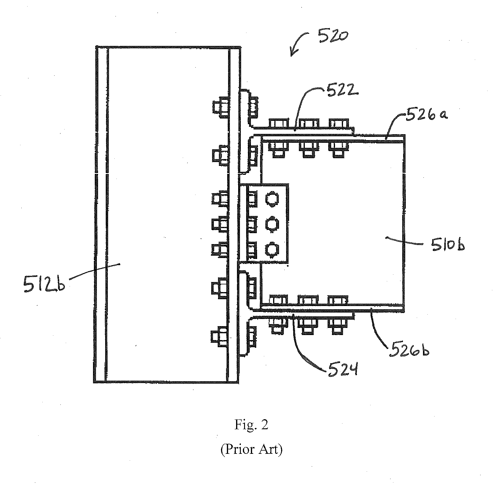
Thus, known and widely used conventional member-to-member connections are generally not designed to accommodate the unique forces experienced at a joint during seismic or other dynamic loading conditions which require inelastic deformation of members of the joint to absorb and dissipate the load to prevent catastrophic failure.
In periods of significant seismic or dynamic loading, most e

Method used


Image

  • Member-to-Member Fuse Connection
  • Member-to-Member Fuse Connection
  • Member-to-Member Fuse Connection

Examples


Embodiment Construction

[0039]The following detailed description of the present invention references the accompanying drawing figures that illustrate specific embodiments in which the invention can be practiced. The embodiments are intended to describe aspects of the present invention in sufficient detail to enable those skilled in the art to practice the invention. Other embodiments can be utilized and changes can be made without departing from the spirit and scope of the present invention. The present invention is defined by the appended claims and, therefore, the description is not to be taken in a limiting sense and shall not limit the scope of equivalents to which such claims are entitled.

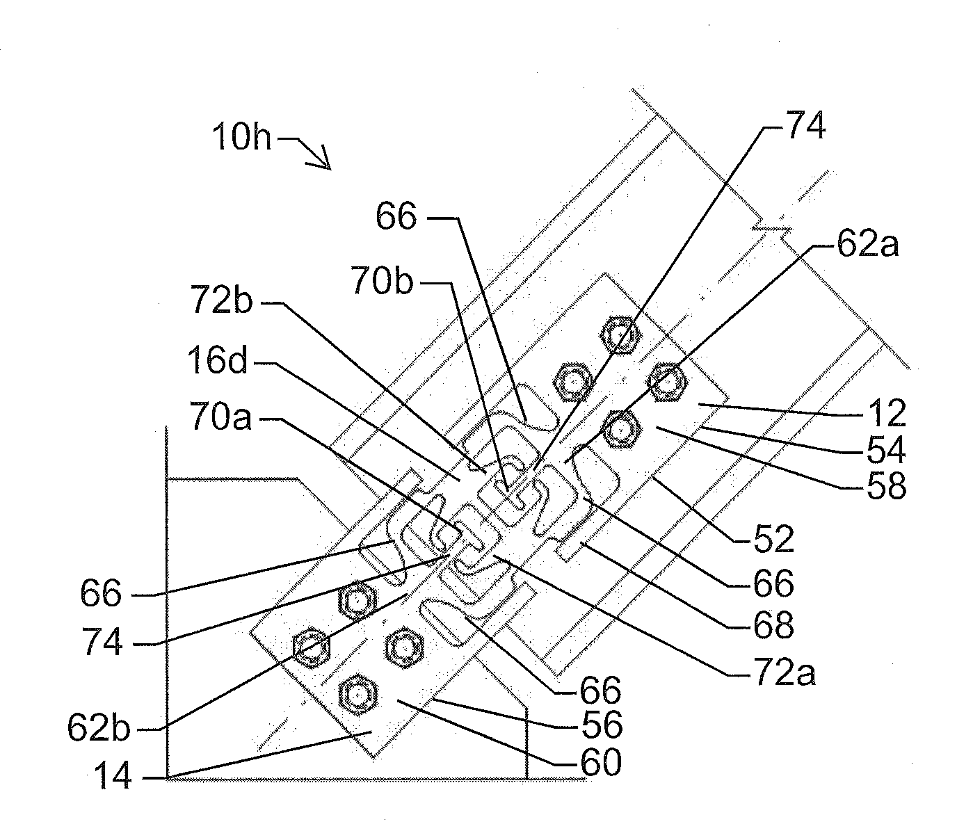
[0040]As illustrated in FIG. 4, a connection bracket 10 of the present invention is shown wherein connection bracket 10 includes a first connection member 12, a second connection member 14 and a fuse member 16 disposed between the first and second connection members 12 and 14. Connection bracket 10 is a member-to-mem...


PUM


Abstract

A member-to-member connection bracket comprising a first connection member for coupling the connection bracket to a first structural member, a second connection member for coupling the connection bracket to a second structural member; and a fuse member disposed between the first connection member and the second connection member, the fuse member comprising at least one of hinge locations. The at least one hinge location provides inelastic deformation at a pre-determined load and the pre-determined load is less than the elastic yield load of a first structural member and a second structural member. The hinge locations may have a reduced thickness. The fuse member may have a tubular cross-section. A connection utilizing the member-to-member connection bracket is also included.

Description

CROSS-REFERENCE TO RELATED APPLICATIONS[0001]This application claims the benefit of U.S. Provisional Patent Application No. 61 / 695,141, filed Aug. 30, 2012 and also claims the benefit of U.S. Provisional Patent Application No. 61 / 734,175 filed Dec. 6, 2012, the entire disclosures of which are hereby incorporated by reference.BACKGROUND OF THE INVENTION[0002]1. Field of the Invention[0003]The present invention relates to a bracket used to facilitate a member-to-member connection for structural load resisting systems, such as, but not limited to, seismic and progressive collapse structural load resisting systems.[0004]2. Description of Related Art[0005]A conventional brace member-to-gusset plate connection 500 is shown in FIG. 1. This type of connection has been used for many years, but is not typically implemented when seismic or other dynamic loading conditions require the connection to sustain inelastic deformation in the components connecting the brace member to the gusset plate t...

Claims


Application Information

Patent Timeline
IPC IPC(8): H01H85/02
CPCH01H85/02H01H85/10H01H85/12H01H85/165H01H85/20Y10T403/4602H01H85/0017E04H9/0237F16B2200/63E04H9/028E04B1/2403
Inventor MCMANUS, PATRICKPUCKETT, JAYPETERSON, JACK
Owner SIMPSON STRONG TIE
Why Eureka
Try Eureka