Wind Turbine System, an Assembling Method of a Wind Turbine System, an Inspecting Method of a Wind Turbine System, and an Operation Method of a Wind Turbine System

Inactive Publication Date: 2014-03-06
HITACHI LTD
View PDF1 Cites 4 Cited by
  • Summary
  • Abstract
  • Description
  • Claims
  • Application Information

AI Technical Summary

Benefits of technology

The present invention provides a wind turbine system that can improve efficiency and lifespan. It also provides an easier method for assembly and maintenance.

Problems solved by technology

The torsion can give rise to a reduction of transmission efficiency of rotating power, or a damage to the main shaft by being added of excess load to the main shaft.
That is, reducing the efficiency of generating electricity or shortening the lifetime of the wind turbine system can be occurred.

Method used


Image

  • Wind Turbine System, an Assembling Method of a Wind Turbine System, an Inspecting Method of a Wind Turbine System, and an Operation Method of a Wind Turbine System
  • Wind Turbine System, an Assembling Method of a Wind Turbine System, an Inspecting Method of a Wind Turbine System, and an Operation Method of a Wind Turbine System
  • Wind Turbine System, an Assembling Method of a Wind Turbine System, an Inspecting Method of a Wind Turbine System, and an Operation Method of a Wind Turbine System

Examples


first embodiment

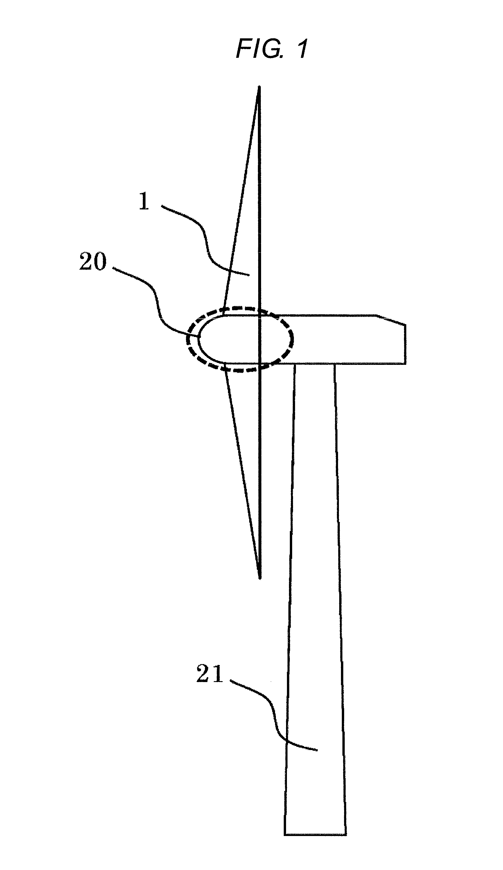
[0024]The first embodiment is explained by FIG. 1 and FIG. 2. As shown in the FIG. 1, a wind turbine system is roughly comprising blades 1 which rotate by receiving wind, a nacelle 20 which supports the blades 1 and receives the load of the blades 1, a tower 21 which supports the nacelle 20. The nacelle 20 is supported by the tower 21 in a substantially horizontal plane and rotatable in the plane, and the nacelle is driven to rotate in the plane depending on wind direction.

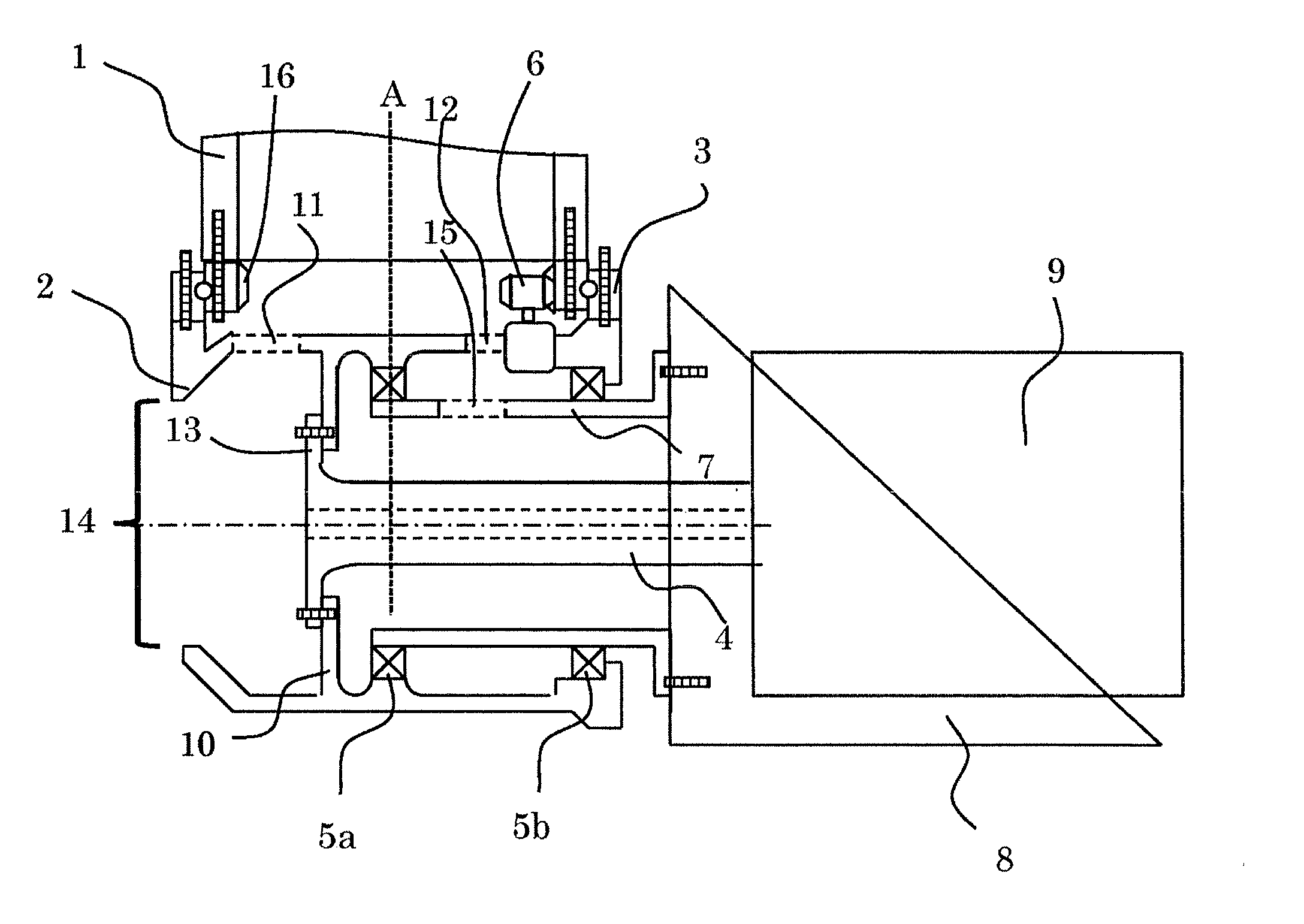
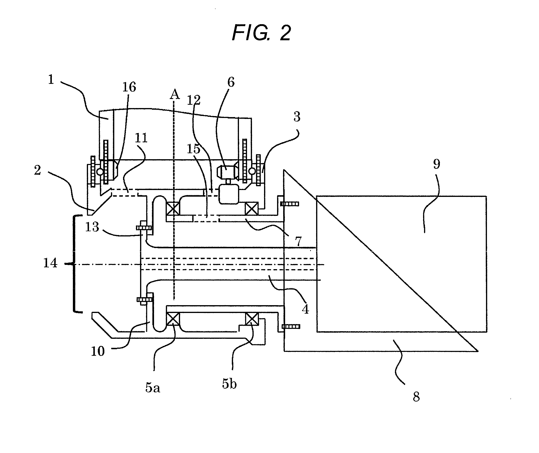
[0025]FIG. 2 is to explain the connecting portion between a hub and a main shaft, and FIG. 2 corresponds to a portion which is shown in FIG. 1 using dotted line. As shown in the FIG. 2, the wind turbine system in this embodiment has blades 1, a hub 2 which supports the blades 1 and rotates with the blades 1, a pitch bearing 3 which adjusts the pitch angle of blades 1 by the drive, a main shaft 4 for transmitting torque which is connected to the hub 2 and is rotated by the rotation of hub 2, a speed-up gear 9 which...

second embodiment

[0037]The second embodiment is explained by FIG. 3. The same structure and the same effect with the first embodiment are omitted. In the first embodiment, the main shaft side flange 13, which is a large-diameter portion, is formed integrally with the main shaft 4, but in this embodiment, a portion corresponding to the flange 13 is formed separately from the main shaft 24 for transmitting torque and the portion is made by a leaf spring (made from different material from the main shaft 24).

[0038]In the embodiment 1, the diameter of the flange 13 is formed smaller than the inner diameter of the opening 14, but in this embodiment, the diameter of the main shaft 24 and the leaf spring are not necessarily to be smaller than the inner diameter of the opening 14 because they are separated material and therefore it is possible to connect with each other in the hub 2 after carrying them into the hub 2.

[0039]Further, in case the power except for rotating power is added via the blades 1 and the...

third embodiment

[0040]The third embodiment is explained by FIG. 4. The same structure and the same effect with the above embodiments are omitted.

[0041]In the first embodiment, the number of the bearings is two, but in this embodiment, the only one bearing 25 is used. The bearing 25 disposed at the rotation center (or the center of gravity) A of blades 1 in the axial direction of the main shaft 4 in the hub 2. In case the only one bearing is used, it is desirable to dispose at substantially rotation center in the axial direction of the main shaft for reducing the load which works on the bearing.

[0042]Incidentally, this embodiment is explained as an alternative of the first embodiment, but of course it is possible to use as an alternative of the second embodiment, that is, this embodiment's feature is also applicable for the case that the main shaft for transmitting torque and the main shaft side flange are separately formed.

[0043]In the above embodiments, the speed-up gear is used, but it's not alwa...


PUM

PropertyMeasurementUnit
Angleaaaaaaaaaa
Diameteraaaaaaaaaa
Sizeaaaaaaaaaa

Abstract

A wind turbine system includes blades which rotate by receiving wind, a nacelle which supports the blades and rotates with the blades, a main shaft for transmitting torque which is connected to the hub and is rotated by the rotation of the hub, and a generator which generates electricity using rotating energy of the main shaft, wherein the main shaft is connected to the hub inside the hub in the axial direction of the main shaft.

Description

BACKGROUND OF THE INVENTION[0001]1. Field of the Invention[0002]The present invention relates to a wind turbine system, an assembling method, an inspecting method, and an operation method of a wind turbine system and especially to a connecting way between a hub and a main shaft.[0003]2. Background Art[0004]A wind turbine system has been introduced broadly as a main tool among renewable energy sources. In the wind turbine system, rotating energy is transmitted to the main shaft via rotation of the hub which supports blades, and a generator is also rotated by the rotation of the main shaft. Thus, electricity is generated in the generator.[0005]In U.S. Pat. No. 4,757,211, an example of a conventional wind turbine system is shown. In this literature, the following components are disposed in a nacelle, that is, a hub which supports blades and rotates with the blades, a main shaft connected to the hub and disposed in the inner diameter side of the hub, a gear box connected to the main sha...

Claims


Application Information

Patent Timeline
IPC IPC(8): F03D1/00
CPCF03D1/00F03D1/0691F05B2240/60F03D15/00F03D80/00Y02E10/72Y10T29/4932Y02E10/728
Inventor TOBINAGA, IKUO
Owner HITACHI LTD
Why Eureka
Try Eureka