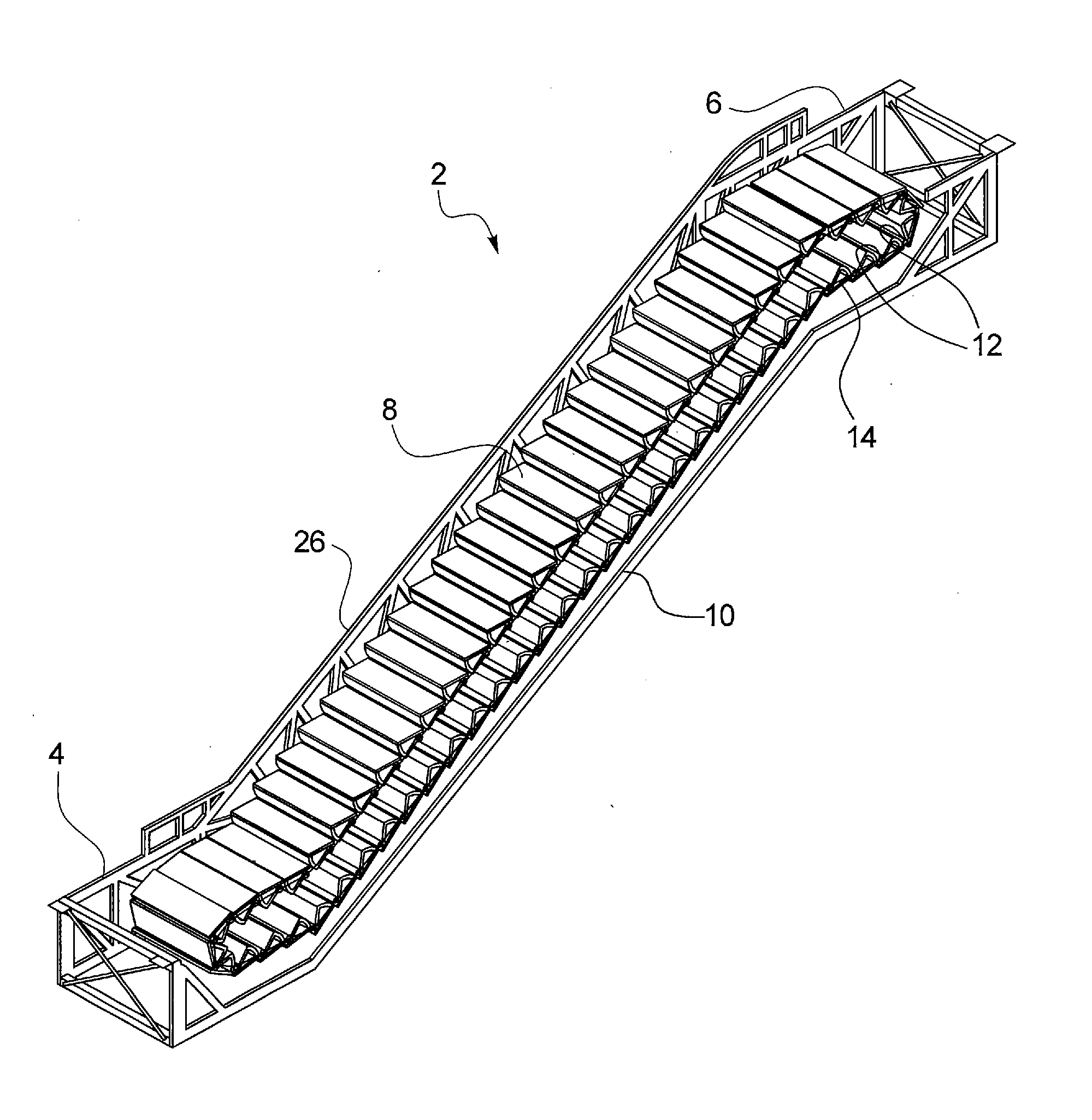
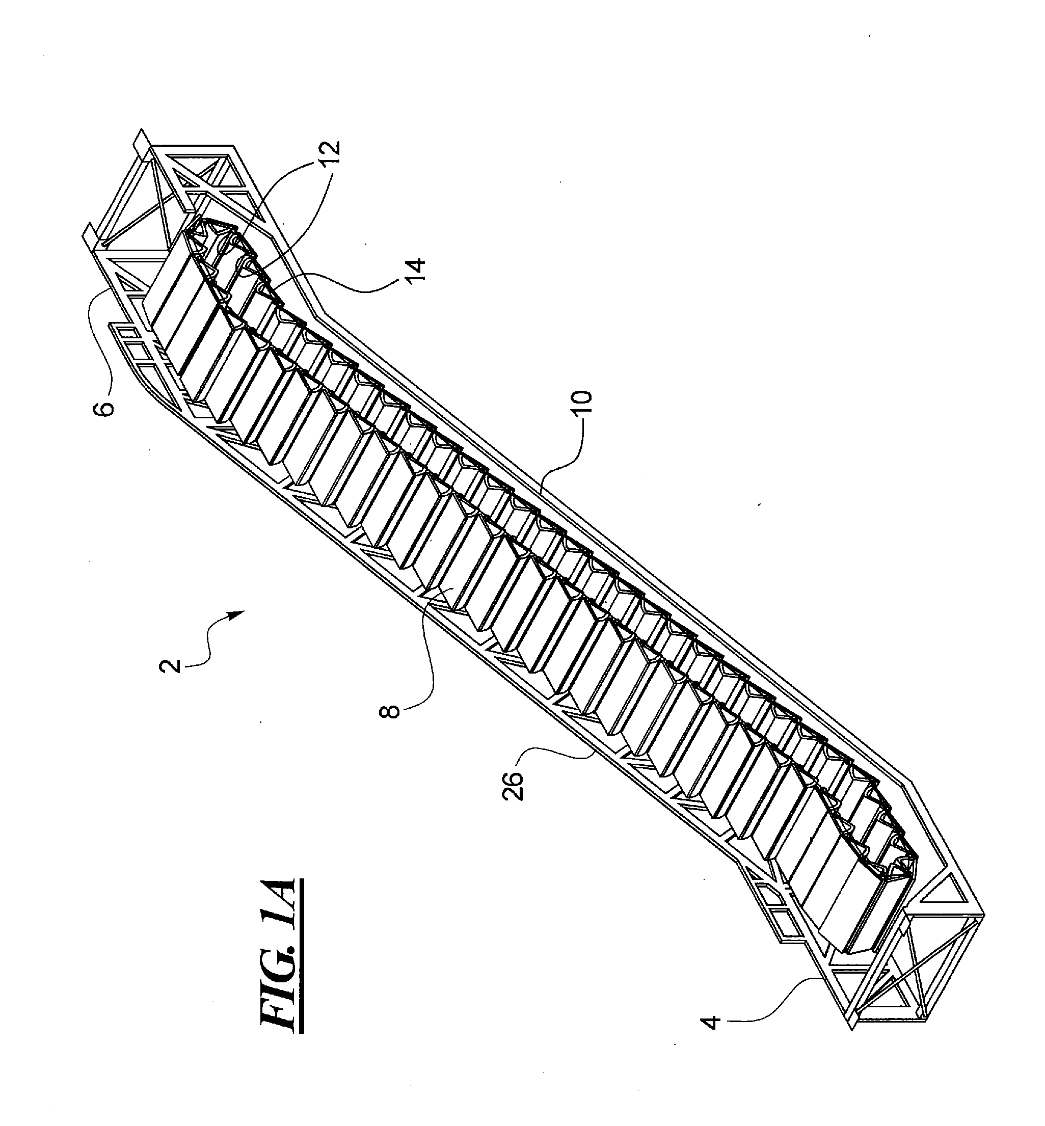
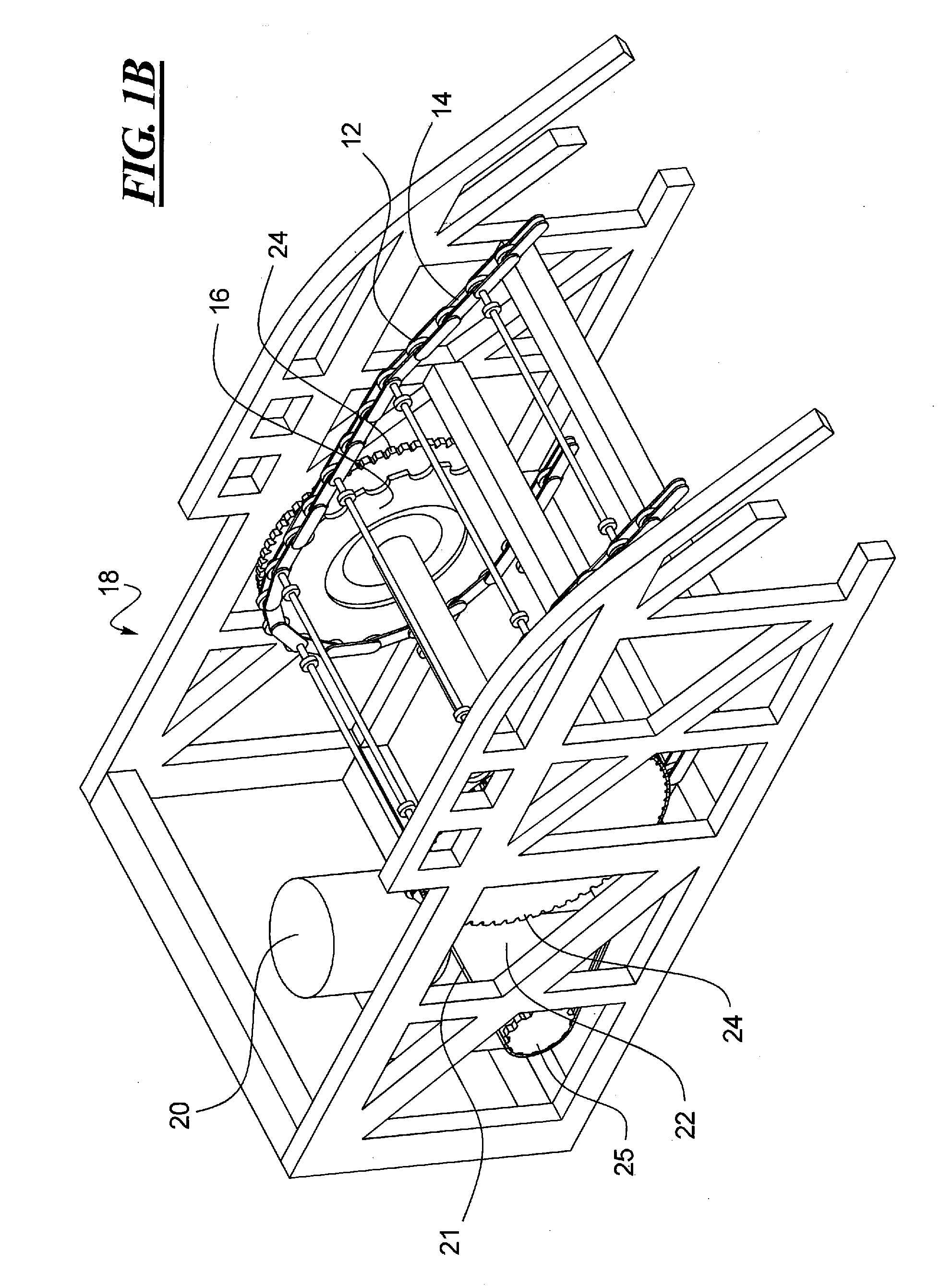
Polygon Compensation Coupling for Chain and Sprocket Driven Systems

a technology of sprocket drive and polygon compensation, which is applied in the direction of couplings, gearings, hoisting equipment, etc., can solve the problems of reducing the lifespan of those components, increasing the overall cost of the associated system, and reducing the polygon

Active Publication Date: 2014-03-06
OTIS ELEVATOR CO
View PDF12 Cites 2 Cited by
  • Summary
  • Abstract
  • Description
  • Claims
  • Application Information

AI Technical Summary

Benefits of technology

[0007]In accordance with one aspect of the present disclosure, a polygon compensation coupling system is disclosed. The polygon compensation coupling system may include a chain sprocket and a main drive. The main drive may be in engagement with the chain sprocket such that the engagement may define a compensation curve to reduce a polygon effect.

Problems solved by technology

The interaction of the step chain with the step chain sprocket often produces fluctuations and vibrations.
These vibrations and fluctuations are often called a polygon effect or a chordal action and not only affect the ride experience of a user (who typically feels these vibrations and fluctuations aboard the passenger conveyor system), but it also causes undesirable friction between the step chain and the step chain sprocket, thereby reducing the lifespan of those components.
For example, due to the increase in the number of the parts (e.g., increase in the number of step chain links and other associated parts, such as, rollers, pins, bushings, link plates, etc., of the step chain, and / or a bigger sprocket), the overall cost of the associated system increases.
This increased wear and tear can additionally reduce the lifespan of the step chain and the step chain sprocket.
Moreover, the aforementioned approach does not address the noise issue discussed above, and may in fact increase the noise due to a greater engagement of the step chain with the step chain sprocket.

Method used


Image

  • Polygon Compensation Coupling for Chain and Sprocket Driven Systems
  • Polygon Compensation Coupling for Chain and Sprocket Driven Systems
  • Polygon Compensation Coupling for Chain and Sprocket Driven Systems

Examples


second embodiment

[0058]Referring now to FIG. 8, a schematic representation of the polygon compensation coupling system 28 is shown as 28′, in accordance with at least some embodiments of the present disclosure. To the extent that the polygon compensation coupling system 28′ is substantially similar to the polygon compensation coupling system 28, only the differences between the two will be described here, for conciseness of expression. As shown, similar to the polygon compensation coupling system 28, the polygon compensation coupling system 28′ may include the step chain 12 having the plurality of step chain links 14 and connecting links 32 that engage with the teeth 30 of the STC sprocket 16 as the step chain moves about the rotating STC sprocket. The STC sprocket 16 also has the three compensation holes 34, which define the compensation curve 42. In contrast to the polygon compensation coupling system 28 in which the MDC sprockets 24 are shown to be circular (or substantially circular), the polygo...

third embodiment

[0061]Turning now to FIGS. 9 and 10A-10B, the polygon compensation coupling system 28 is shown as 28″, in accordance with at least some embodiments of the present disclosure. In contrast to the polygon compensation coupling systems 28 and 28′, the polygon compensation coupling system 28″ employs a stationary plate 50 having a circumference that is defined by the determined compensation curve 42 above, as well as engagement surfaces (e.g., linear slots) 51 in the STC sprocket 16 and corresponding engagement surfaces (e.g., linear slots) 52 in the MDC sprockets 24 (only the linear slots in the MDC sprocket are visible in FIG. 9), all of which may be mounted to center around a common midpoint 54. The MDC sprocket 24 may be connected to the STC sprocket 16 by a way of a system fixation 56.

[0062]By virtue of the compensation curve 42 being fixed, it drives an engagement point 58 in a manner that the step chain 12 maintains a substantially constant linear speed when the MDC sprocket 24 an...


PUM


Abstract

A polygon compensation coupling system for reducing a polygon effect in a chain driven system is disclosed. The polygon compensation coupling system may include a chain sprocket and a main drive in engagement with the chain sprocket, such that the engagement defines a compensation curve to reduce the polygon effect.

Description

FIELD OF THE DISCLOSURE[0001]The present disclosure generally relates to chain and sprocket driven systems and, more particularly, relates to minimizing a polygon effect associated with chain and sprocket driven systems, such as, passenger conveyor systems.BACKGROUND OF THE DISCLOSURE[0002]Several types of passenger conveyor systems, such as, escalators, moving walkways, moving sidewalks, etc. are widely used these days to effectively transport pedestrian traffic (or other objects) from one location to another. Areas of usage of these passenger conveyor systems often include airports, hotels, shopping malls, museums, railway stations and other public buildings. Such passenger conveyor systems typically have two landings (e.g., a top landing and a bottom landing) that bridge a truss structure. Moving handrails, as well as a plurality of steps / treads guided by a step chain (also called an escalator chain) in a loop transport the pedestrian traffic between the two landings. The step ch...

Claims


Application Information

Patent Timeline
Patent Type & Authority Applications(United States)
IPC IPC(8): F16H7/20
CPCF16H7/20B66B23/022F16H2007/0865F16H2007/0859F16H7/1227F16H2007/0893F16H7/12B66B23/02B66B23/18
Inventor SRB-GAFFRON, WALTERTUREK, ALEXANDER
Owner OTIS ELEVATOR CO
Why Eureka
Try Eureka