Floating fastener mounting structure and method

Inactive Publication Date: 2014-03-13
HANWIT PRECISION IND LTD
View PDF23 Cites 10 Cited by
  • Summary
  • Abstract
  • Description
  • Claims
  • Application Information

AI Technical Summary

Benefits of technology

[0012]In an alternate form of the present invention, the aforesaid C-shaped retainer is eliminated, and the lock screw is fixedly mounted with a cap member that is axially slideably coupled to the mounting socket.

Problems solved by technology

The lock screws of the fastening devices may fall from the metal panel members and missed easily due to user's negligence during a metal pa

Method used


Image

  • Floating fastener mounting structure and method
  • Floating fastener mounting structure and method
  • Floating fastener mounting structure and method

Examples


Example

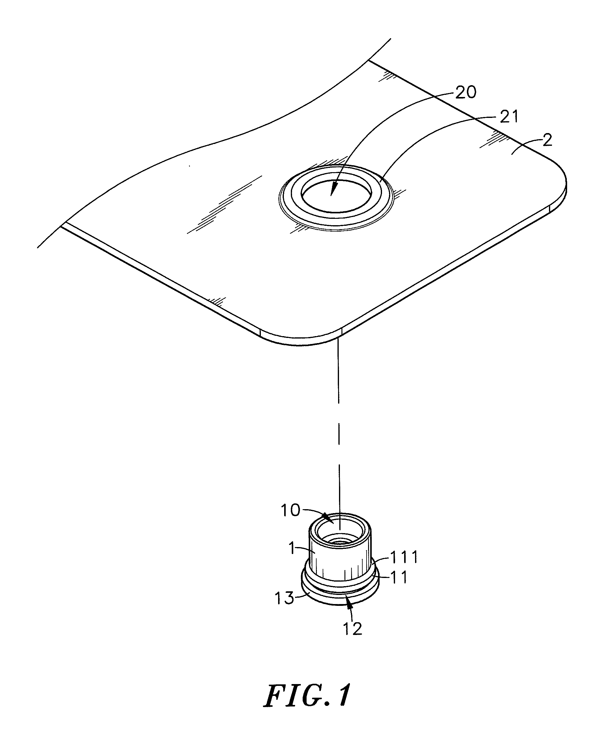
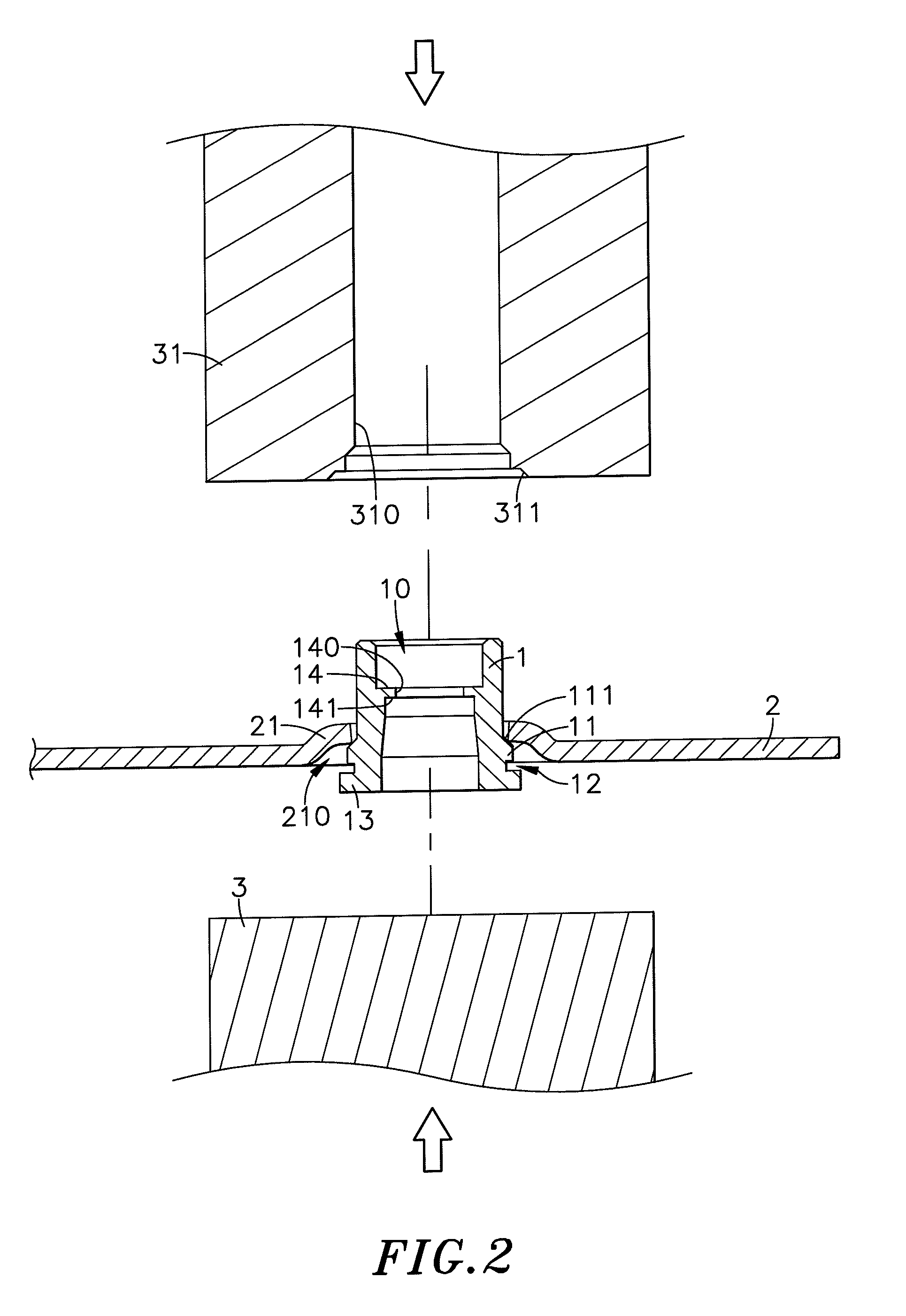
[0024]Referring to FIGS. 1, 2 and 3, a mounting socket mounting structure of a floating fastener in accordance with the present invention is shown. The mounting socket mounting structure comprises a mounting socket 1, and a metal panel member 2.

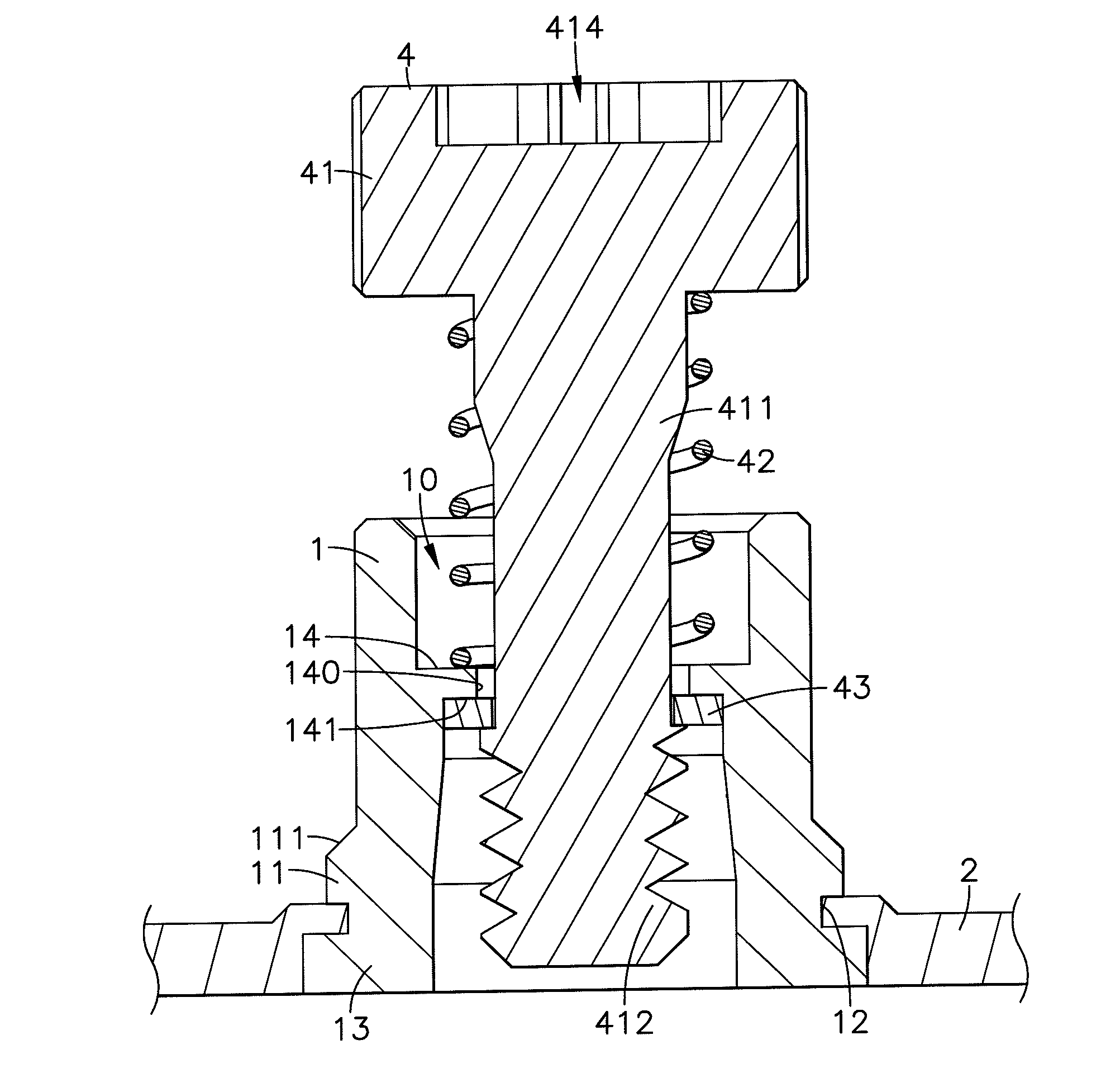
[0025]The mounting socket 1 is an open-ended cylindrical member comprising a center hole 10 vertically extending through opposing top and bottom sides thereof, an annular step 11 protruding from and extending around the outer perimeter thereof near the bottom side and spaced above the bottom side at a predetermined distance, and an annular locating groove 12 extending around the outer perimeter and abutted against the bottom side of the annular step 11. The annular step 11 defines a downwardly and outwardly sloping top surface 111.

[0026]The metal panel member 2 comprises a mounting through hole 20, and a convex wall portion 21 disposed around the mounting through hole 20 and defining a bottom accommodation space 210. The mounting through hole...


PUM

PropertyMeasurementUnit
Diameteraaaaaaaaaa
Perimeteraaaaaaaaaa

Abstract

A floating fastener mounting structure and method is disclosed to include a metal panel member defining a convex wall portion and a mounting through hole at the convex wall portion, a mounting socket defining a center hole, an annular step around the outer perimeter and an annular locating groove around the outer perimeter and at the bottom side of the annular step and being riveted to the metal panel member to force the annular locating groove into engagement with the convex wall portion tightly, a spring member mounted in the mounting socket, and a lock screw floatably supported on the spring member in the mounting socket for detachably locking the metal panel member to an external metal panel member.

Description

BACKGROUND OF THE INVENTION[0001]1. Field of the Invention[0002]The present invention relates to floating fastener mounting technology and more particularly, to the fixation between a mounting socket of a floating fastener and a metal panel member using stamping technique, which provides high shear strength.[0003]2. Description of the Related Art[0004]When joining metal panel members, fastening devices respectively formed of a lock screw, a rotary knob and a washer may be used. During application, the lock screw, rotary knob and washer of each fastening device are assembled and then mounted at a first metal panel member. When fastening the first metal panel member to a second metal panel member, rotate the rotary knob of each fastening device to drive the respective lock screw into a respective mounting screw hole at the second metal panel member, and then use a hand tool to fasten tight the lock screw. This multiple metal panel member fastening method can be used in a machine tool ...

Claims


Application Information

Patent Timeline
IPC IPC(8): F16B39/24B23P11/00
CPCF16B5/0208Y10T29/49948
Inventor TSENG, YING-CHIH
Owner HANWIT PRECISION IND LTD
Why Eureka
Try Eureka