Detection apparatus and method

a technology of detection apparatus and method, which is applied in the detection of fluid at leakage point, manufacturing tools, instruments, etc., can solve problems such as the leakage of the outer wall of the flexible pip

Active Publication Date: 2014-03-13
GE OIL & GAS UK LTD
View PDF9 Cites 18 Cited by
  • Summary
  • Abstract
  • Description
  • Claims
  • Application Information

AI Technical Summary

Benefits of technology

[0008]Certain embodiments of the invention provide the advantage that a defect within a pipe body can be detected without requiring periodic visual inspection. Defects can then be repaired, or the pipe body replaced. Detectable defects include a breach of the outer wall of a flexible pipe and the ingress of seawater into a pipe body annulus. Certain embodiments can also provide an indication of changes in the condition of the pipe body, for instance due to crushing or bending applied to the pipe body, or variation in temperature along the length of the pipe body.

Problems solved by technology

Detectable defects include a breach of the outer wall of a flexible pipe and the ingress of seawater into a pipe body annulus.

Method used


Image

  • Detection apparatus and method
  • Detection apparatus and method
  • Detection apparatus and method

Examples


first embodiment

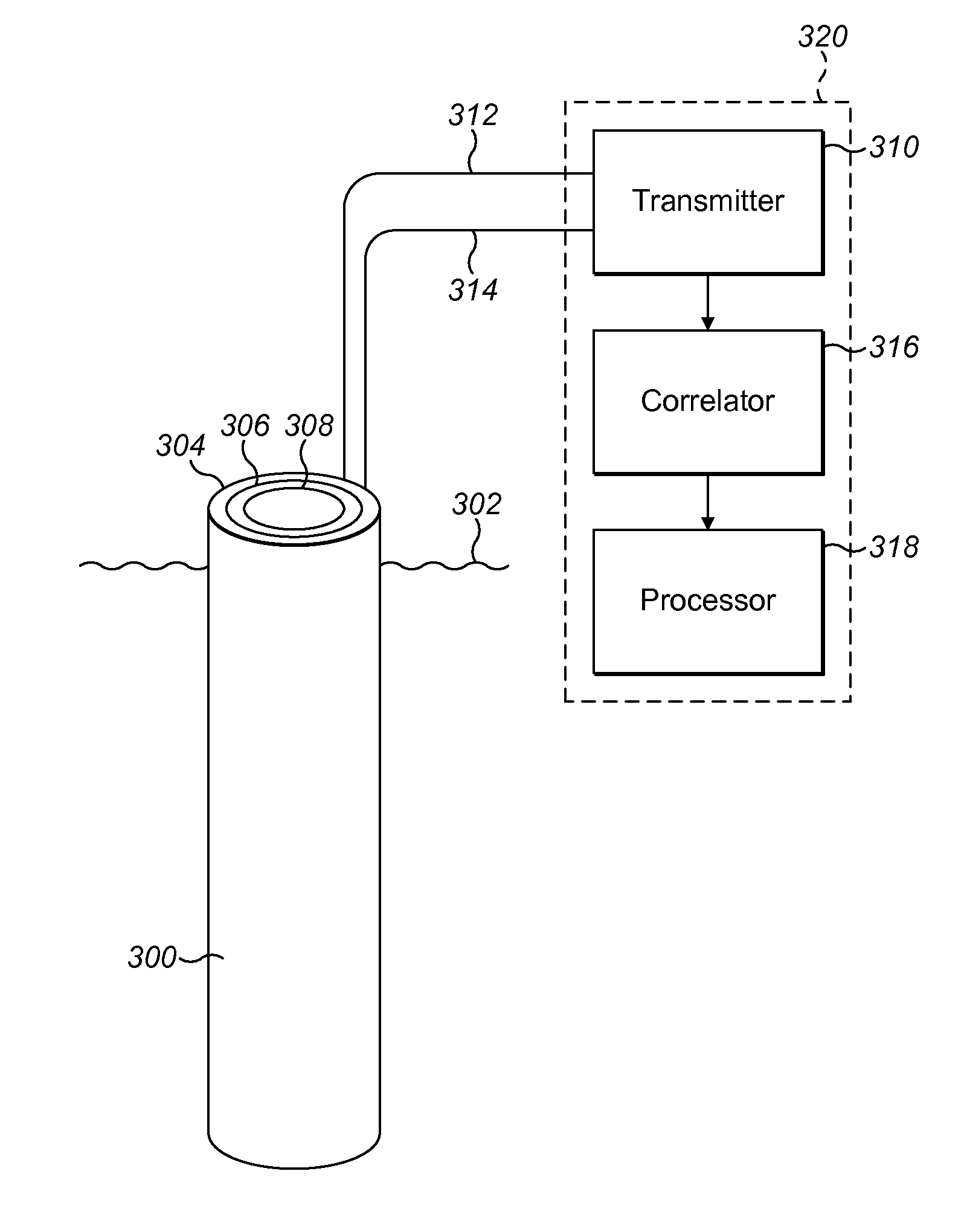
[0052]FIG. 3 illustrates a detection apparatus in accordance with the present invention coupled to a flexible pipe body. The detection apparatus is arranged to detect a change to a flexible pipe body which may indicate either a defect (and in particular a breach allowing seawater or other fluids into the pipe body annulus) or certain forms of change of condition as discussed above. The detection apparatus may be coupled to a warning system arranged to provide an output signal to an operator of the flexible pipe alerting the operator to potential damage to the pipe. The output signal may, for instance, be a visual or audible alarm.

[0053]FIG. 3 shows a flexible pipe 300, which as discussed above may form a riser. The pipe is at least partially surrounded by seawater, schematically illustrated by the pipe extending below the surface level 302 of the sea. As discussed above, a flexible pipe body is constructed from multiple layers of polymer barrier, including an outer seawater resistan...

second embodiment

[0073]Unlike the predominantly electron flow conduction in metals, the electrical conduction in seawater is dependent on ion mobility, and this leads to significant variation in observed conductivity with the frequency of the applied measurement excitation. This is shown schematically in the FIG. 6 which shows relative attenuation of an applied alternating current signal at various low frequencies and between electrodes spaced at 10 m, 100 m, and 1 Km. the present invention takes advantage of the attenuation data of FIG. 6 by applying frequency agile excitation of the impedance monitor 410, comparing the results obtained at various frequencies, and from that information determining an approximate location of the breach. In certain embodiments the excitation frequency of the impedance monitor is in the range 10 Hz to 1 kHz. In other embodiments the maximum excitation frequency of the impedance monitor may be 100 kHz. It will be appreciated by the skilled person that the detection sys...


PUM

PropertyMeasurementUnit
frequenciesaaaaaaaaaa
internal diameteraaaaaaaaaa

Abstract

A first embodiment of a detection apparatus arranged to detect defects within a flexible pipe body comprises a signal generator, a receiver, a correlator and a processor. A second embodiment of a detection apparatus arranged to detect defects within a flexible pipe at least partially surrounded by seawater comprises an impedance monitor and a processor. Methods of detecting defects within a flexible pipe body, a pipeline apparatus and methods of forming pipeline apparatuses are also disclosed.

Description

FIELD OF THE INVENTION[0001]The present invention relates to a detection apparatus and method. In particular, the present invention relates to a detection apparatus arranged to detect defects within a flexible pipe body, and a method of detecting defects or changes of condition of a pipe body. Particular embodiments relate to a flexible pipe comprising a flexible pipe body and the detection apparatus, a method of forming such a flexible pipe, and a method of operating such a flexible pipe. Certain embodiments of the present invention are also arranged to detect a change in condition of a pipe body.BACKGROUND OF THE INVENTION[0002]Traditionally flexible pipe is utilised to transport production fluids, such as oil and / or gas and / or water, from one location to another. Flexible pipe is particularly useful in connecting a sub-sea location (which may be deep underwater, say 1000 metres or more) to a sea level location. The pipe may have an internal diameter of typically up to around 0.6 ...

Claims


Application Information

Patent Timeline
Patent Type & Authority Applications(United States)
IPC IPC(8): G01M3/40F16L55/07
CPCF16L55/07G01M3/40G01N17/02G01M3/18Y10T29/49826
Inventor GRAHAM, GEOFFREY STEPHENHARLEY, PHILLIP EDWARDSHEPHARD, WILLIAM JAMES
Owner GE OIL & GAS UK LTD
Why Eureka
Try Eureka