
System and method for modular transportation of a welding system

a transportation device and welding system technology, applied in the field of welding systems, can solve the problems of high shipping fees for transportation devices, inability to enable the purchaser or end-user, and heavy final products that cannot be changed by the purchaser or end-user, and achieve the effect of reducing shipping and/or assembly costs

Active Publication Date: 2014-03-13
ILLINOIS TOOL WORKS INC
View PDF30 Cites 5 Cited by
  • Summary
  • Abstract
  • Description
  • Claims
  • Application Information

AI Technical Summary

Benefits of technology

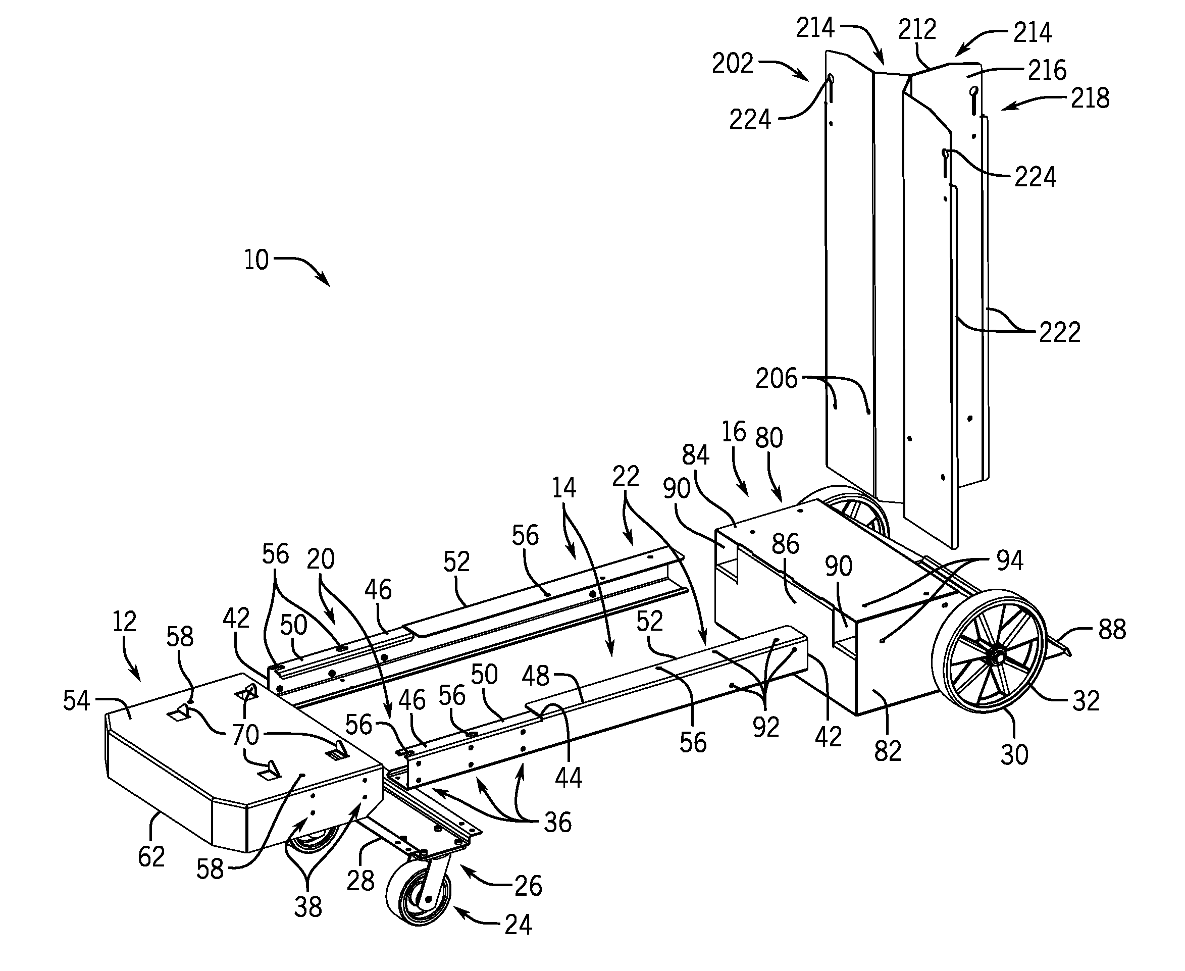
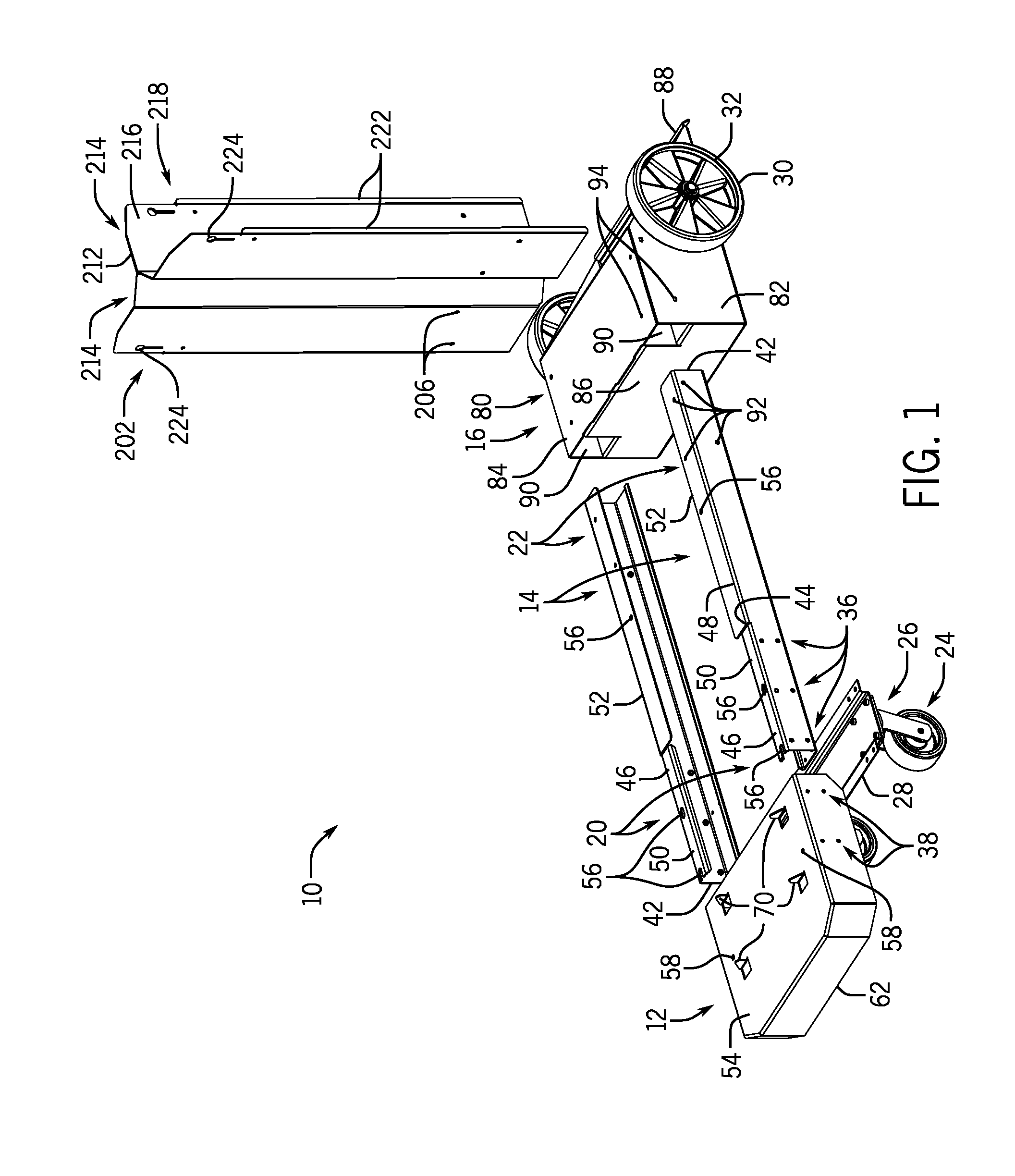
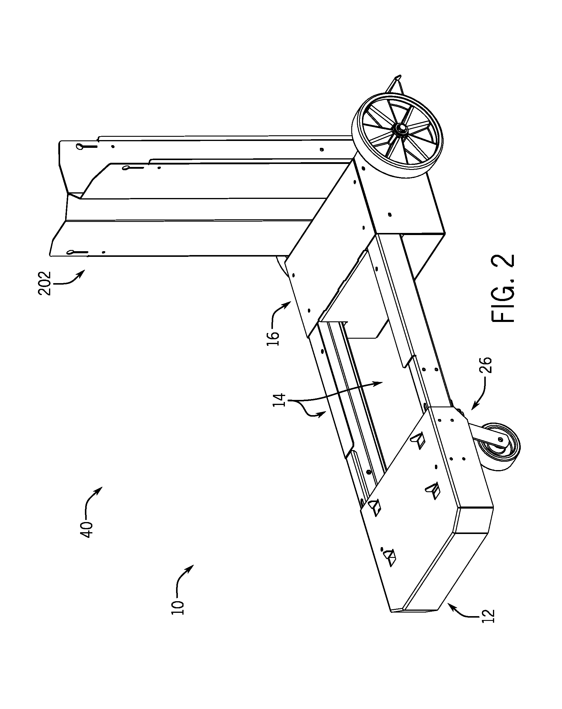
The present disclosure is a modular welding component transportation system that can be easily assembled by a purchaser or end-user. The system includes a front panel, a wheel assembly, and one or more rails. The front panel and wheel assembly are designed to be coupled together by the rail or plural rails. The front panel includes a support platform for a welding system component and the wheel assembly includes a plurality of wheels. The system also includes an adjustable rail that can be coupled with the front panel and / or wheel assembly in different configurations. Additionally, the system may include additional wheels for added stability and flexibility. The technical benefit of this invention is a modular system that simplifies the transportation of welding system components, making it easier to assemble and adjust for different needs.

Problems solved by technology

The assembly process generally includes welding the components of the transportation device together, resulting in a bulky and often heavy final product that cannot be changed by the purchaser or end-user.
This traditional assembly sequence generally results in costly shipping fees for shipping the transportation device and does not enable the purchaser or end-user to customize the transportation device to fit their needs.

Method used


Image

  • System and method for modular transportation of a welding system
  • System and method for modular transportation of a welding system
  • System and method for modular transportation of a welding system

Examples


Embodiment Construction

[0012]The present disclosure is directed to a modular transportation device or running gear that may be particularly well suited for transporting welding systems and / or welding system accessories. As such, the transportation device may include a platform to accommodate a power source or other component (e.g., a cooler) of a welding system. The platform may be formed from a front panel and one or more rails such that a length of the platform may be adjustable into different configurations to enable the transportation device to accommodate multiple welding system component sizes (e.g. power supply sizes). The one or more rails of the system may each include between approximately 2 and 10 sets of holes (or other coupling features) that facilitate coupling with the front panel, a wheel assembly (including rear wheels), front wheels, or a combination thereof, with respect to the rail or rails. Indeed, one or more of each of the front panel, the wheel assembly, and the front wheels may be...


PUM

PropertyMeasurementUnit
lengthaaaaaaaaaa
perimeteraaaaaaaaaa
sinusoidal shapeaaaaaaaaaa

Abstract

Present embodiments include a modular welding component transportation system. The system includes a front panel and a wheel assembly. The front panel includes a support platform configured to support a welding system component and the wheel assembly includes a first plurality of wheels. The system also includes a rail configured to adjustably couple with the front panel proximate a first end of the rail and configured to couple with the wheel assembly proximate a second end of the rail. Locating surfaces of the wheel assembly are configured to receive and align the rail for engagement with walls of the wheel assembly. The system further includes a second plurality of wheels configured to be coupled with the front panel or proximate the first end of the rail.

Description

CROSS-REFERENCE TO RELATED APPLICATION[0001]This application claims priority from and the benefit of U.S. Provisional Application Ser. No. 61 / 698,035, entitled “MODULAR TRANSPORTATION DEVICE FOR A WELDING SYSTEM,” filed Sep. 7, 2012, which is hereby incorporated by reference in its entirety for all purposes.BACKGROUND[0002]The present disclosure relates generally to the field of welding systems, and more particularly to a welding system transportation device.[0003]Transportation devices (e.g., carts, dollies, running gear) for welding systems are generally assembled in a factory setting and subsequently delivered to the purchaser. The assembly process generally includes welding the components of the transportation device together, resulting in a bulky and often heavy final product that cannot be changed by the purchaser or end-user. This traditional assembly sequence generally results in costly shipping fees for shipping the transportation device and does not enable the purchaser or...

Claims


Application Information

Patent Timeline
Patent Type & Authority Applications(United States)
IPC IPC(8): B62B3/10B23P19/00
CPCB23P19/00B62B3/10B62B3/02B62B2202/022B62B2202/48B62B2205/006B62B2206/02Y10T29/49826
Inventor SAMMONS, MICHAEL ALLENSONTAKKE, PRAVIN PRABHAKARRAO
Owner ILLINOIS TOOL WORKS INC
Learn More