Current sensor

a current sensor and sensor technology, applied in the field of current sensors, can solve the problems of unrealistic mounting accuracy and manufacturing cost, and achieve the effects of reducing the electrical reducing the resistance of the first conductor, and suppressing heat generation

Active Publication Date: 2014-03-13
ALPS ALPINE CO LTD
View PDF1 Cites 23 Cited by
  • Summary
  • Abstract
  • Description
  • Claims
  • Application Information

AI Technical Summary

Benefits of technology

[0014]In the current sensor according to the present invention, preferably, each of the first conductor and the second conductor includes a thin plate portion and thick plate portions at both sides of the thin plate portion, and the first magnetoelectric transducer and the second magnetoelectric transducer are arranged such that the thin plate portion of the first conductor is interposed therebetween. According to this configuration, the electrical resistance of the first conductor is reduced by the thick plate portion, and thus it is possible to suppress heat generation by flowing of a measured current. As a result, it is possible to achieve higher current measurement accuracy.

Problems solved by technology

However, to achieve sufficiently high current measurement accuracy, it is necessary to arrange the magnetic sensor such that the magnetic sensor is tilted relative to the current paths, but this arrangement is not realistic in terms of mounting accuracy and manufacturing cost.

Method used


Image

  • Current sensor
  • Current sensor
  • Current sensor

Examples


embodiment 1

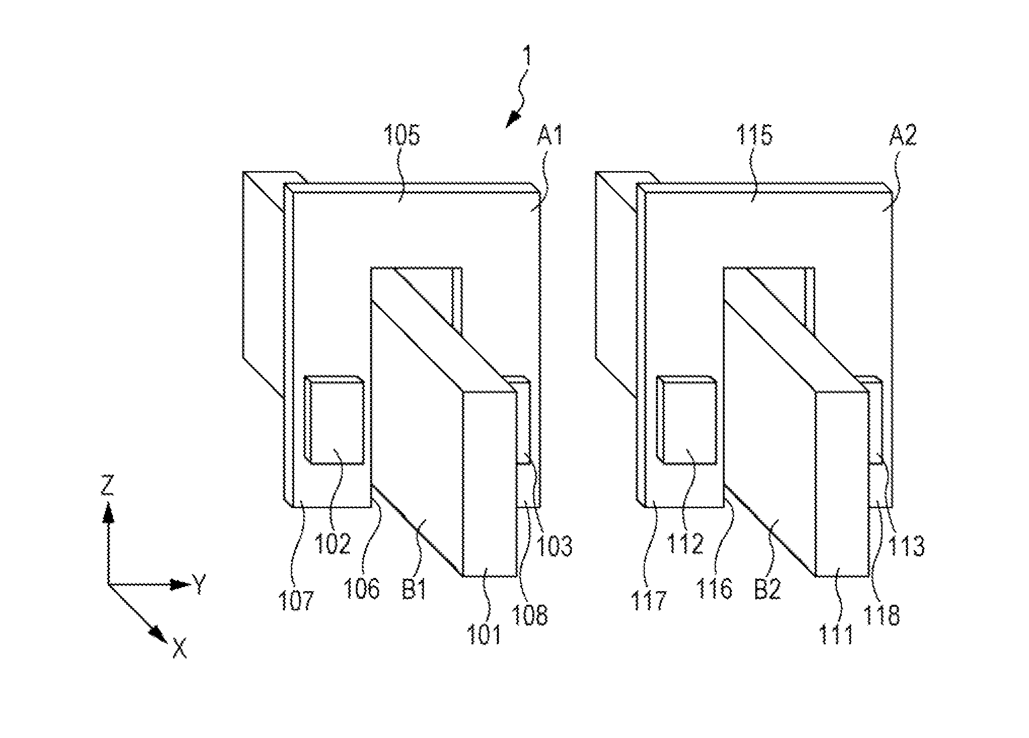
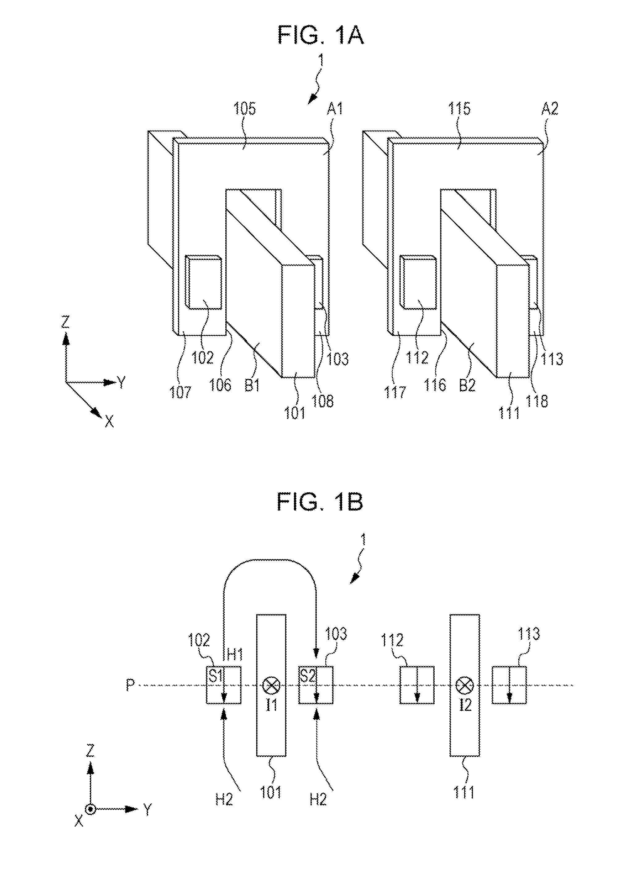
[0031]In this embodiment, a first aspect of a current sensor will be described. FIGS. 1A and 1B are schematic diagrams showing a configuration example of a current sensor 1 according to the embodiment. FIG. 1A is a perspective view schematically showing a configuration of the current sensor 1, and FIG. 1B is a schematic diagram showing a positional relationship between conductors 101 and 111 and magnetoelectric transducers 102, 103, 112, and 113 in the current sensor 1.

[0032]As shown in FIG. 1A, the current sensor 1 includes the conductor (first conductor) 101 and the conductor (second conductor) 111 that form current paths. The conductors 101 and 111 extend in a first direction (X axis direction) and have flat plate shapes parallel to each other. The conductors 101 and 111 have predetermined thicknesses in a second direction (Y axis direction) orthogonal to the first direction and have predetermined widths in a third direction (Z axis direction) orthogonal to the first direction an...

embodiment 2

[0043]In this embodiment, a second aspect of the current sensor will be described. FIGS. 4A and 4B are schematic diagrams showing a configuration example of a current sensor 1a according to the embodiment. FIG. 4A is a perspective view schematically showing a configuration of the current sensor 1a, and FIG. 4B is a schematic diagram showing a positional relationship between conductors 101 and 111, magnetoelectric transducers 102, 103, 112, and 113, and magnetic shields (magnetic yokes) 121, 122, and 123 in the current sensor 1a. It should be noted that many of the components of the current sensor 1a according to the embodiment are the same as the components of the current sensor 1 according to Embodiment 1. Thus, the components that are the same as those of the current sensor 1 are designated by the same reference signs, and the detailed description thereof is omitted.

[0044]As shown in FIG. 4A, in the current sensor 1a according to the embodiment, the thin plate-shaped magnetic shie...

embodiment 3

[0048]In this embodiment, a third aspect of the current sensor will be described. FIGS. 5A and 5B are schematic diagrams showing a configuration example of a current sensor 1b according to the embodiment. FIG. 5A is a perspective view schematically showing a configuration of the current sensor 1b, and FIG. 5B is a schematic diagram showing a positional relationship between conductors 101 and 111, magnetoelectric transducers 102, 103, 112, and 113, and magnetic shields 131, 132, 133, and 134 in the current sensor 1b. It should be noted that many of the components of the current sensor 1b according to the embodiment are the same as the components of the current sensor 1 according to Embodiment 1. Thus, the components that are the same as those of the current sensor 1 are designated by the same reference signs, and the detailed description thereof is omitted.

[0049]As shown in FIG. 5A, the current sensor 1b according to the embodiment also includes the thin plate-shaped magnetic shields...


PUM


Abstract

A current sensor includes a first conductor and a second conductor arranged so as to form current paths parallel to each other; a circuit board arranged such that a surface thereof is perpendicular to the current paths; and a first magnetoelectric transducer and a second magnetoelectric transducer arranged on the surface of the circuit board such that the first conductor is interposed therebetween. The first conductor, the second conductor, the first magnetoelectric transducer, and the second magnetoelectric transducer are located on a same plane.

Description

CLAIM OF PRIORITY[0001]This application is a Continuation of International Application No. PCT / JP2013 / 060227 filed on Apr. 3, 2013, which claims benefit of Japanese Patent Application No. 2012-112340 filed on May 16, 2012. The entire contents of each application noted above are hereby incorporated by reference.BACKGROUND OF THE INVENTION[0002]1. Field of the Invention[0003]The present invention relates to a current sensor capable of measuring, in a non-contact manner, a current flowing through a conductor, and particularly relates to a current sensor that detects a magnetic field generated by a current and measures a current value.[0004]2. Description of the Related Art[0005]A current sensor capable of measuring a current value in a non-contact manner on the basis of an induction field generated by a measured current, has been put to practical use. The current sensor includes a magnetoelectric transducer for detecting an induction field, and calculates a current value of a measured ...

Claims


Application Information

Patent Timeline
Patent Type & Authority Applications(United States)
IPC IPC(8): G01R19/00G01R33/02
CPCG01R33/02G01R19/00G01R15/207G01R15/20
Inventor TAMURA, MANABU
Owner ALPS ALPINE CO LTD
Why Eureka
Try Eureka