
System and method that minimizes hazards of blind spots while driving

Inactive Publication Date: 2014-03-13
ASSAF MUSAID A
View PDF7 Cites 38 Cited by
  • Summary
  • Abstract
  • Description
  • Claims
  • Application Information

AI Technical Summary

Benefits of technology

The blind-spot detection and collision avoidance system for automobiles described in this patent consists of a blind-spot camera, a rear view mirror assembly, and a tracking processor. The blind-spot camera is located in the side-view mirror and provides a wider perspective compared to the side-view mirror. The rear view mirror assembly includes a mirrored portion and a display portion that shows the objects detected in the blind spots covered by the blind-spot camera. The tracking processor receives the image from the blind-spot camera and detects objects within the camera's field of view and within a predetermined range from the camera. When an object is detected, the processor sends a display signal to the display portion of the rear view mirror assembly to alert the driver. The object detector is also responsive to an external signal indicating that the automobile is preparing to change driving lanes. This system helps improve safety and prevent accidents by alerting the driver when they may be blind-spoted or may collude with another object on the road.

Problems solved by technology

A known problem is that the mirrors do not provide complete 180 degree around the sides and back of the automobile.
It is, therefore, dangerous for the driver to change lanes by only using the mirrors.
However, as recognized by the present inventor, the shaped mirror provides a distorted view and therefore can cause some confusion to the driver, which is especially dangerous when there is little reaction time, such as when the driver is in executing an avoidance maneuver.
However, once again this can be dangerous since the driver has to take his eyes of the road in front of him.
However as recognized by the present inventor, this system is active all the time, and neither assists in alerting the driver when the system determines that the driver is attempting to change lanes nor assists the driver by tracking the vehicle in the blind spot.

Method used


Image

  • System and method that minimizes hazards of blind spots while driving
  • System and method that minimizes hazards of blind spots while driving
  • System and method that minimizes hazards of blind spots while driving

Examples


Embodiment Construction

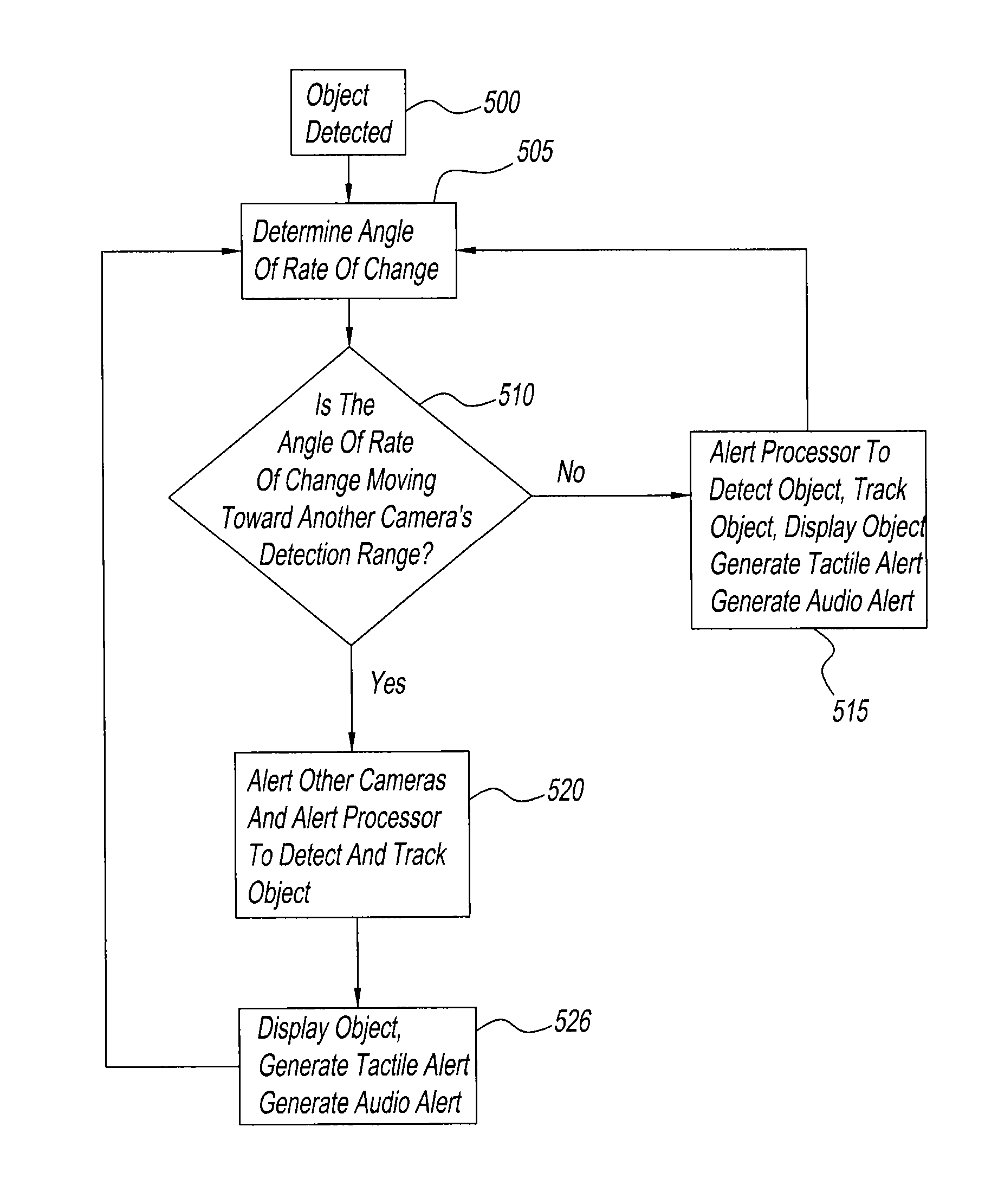
[0026]The present inventor recognized that conventional systems do not assist a driver in inspecting a blind spot without distorting the view or requiring the driver to turn his head. In light of this deficiency, an automobile blind spot detection and tracking mechanism is presented.

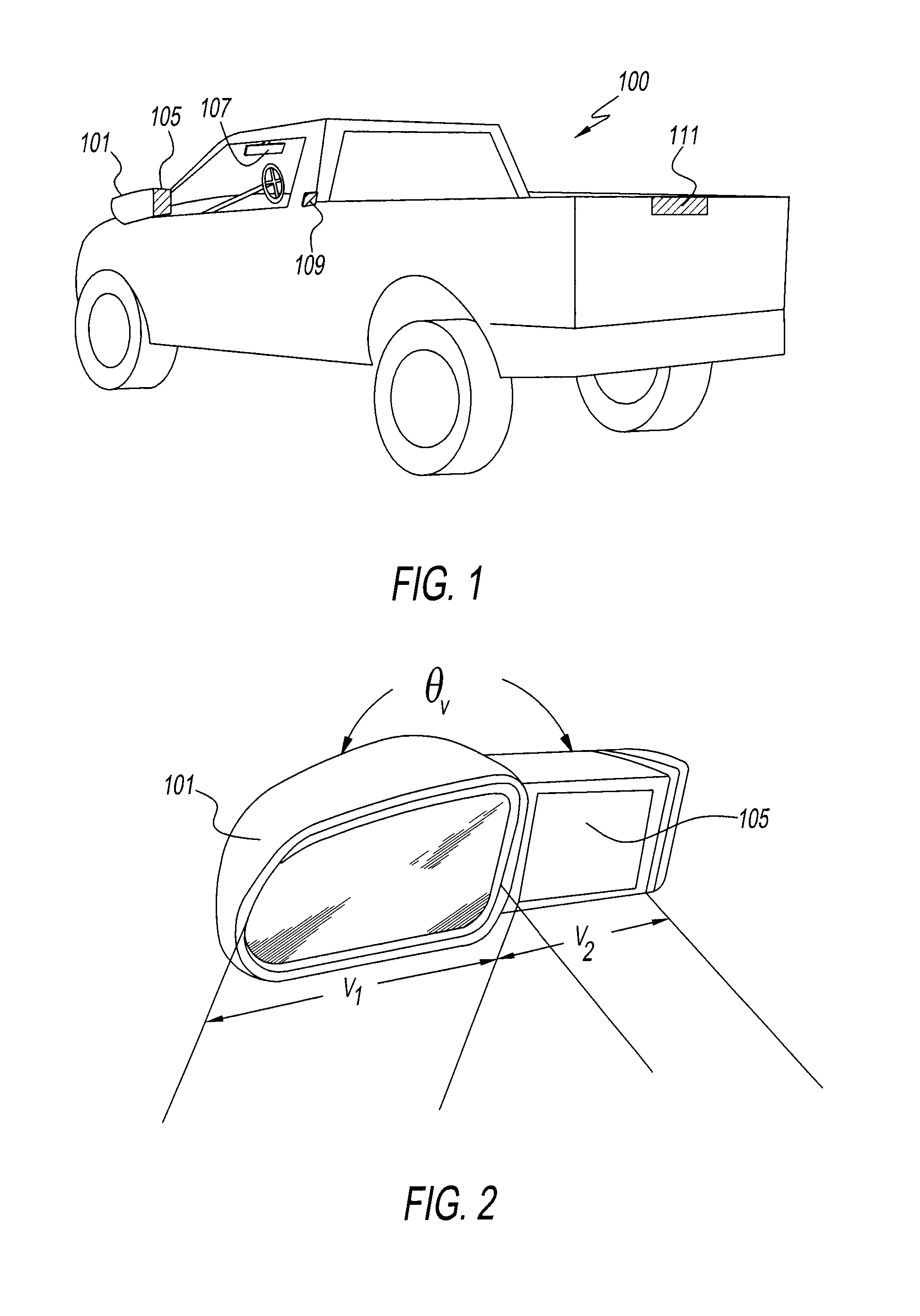
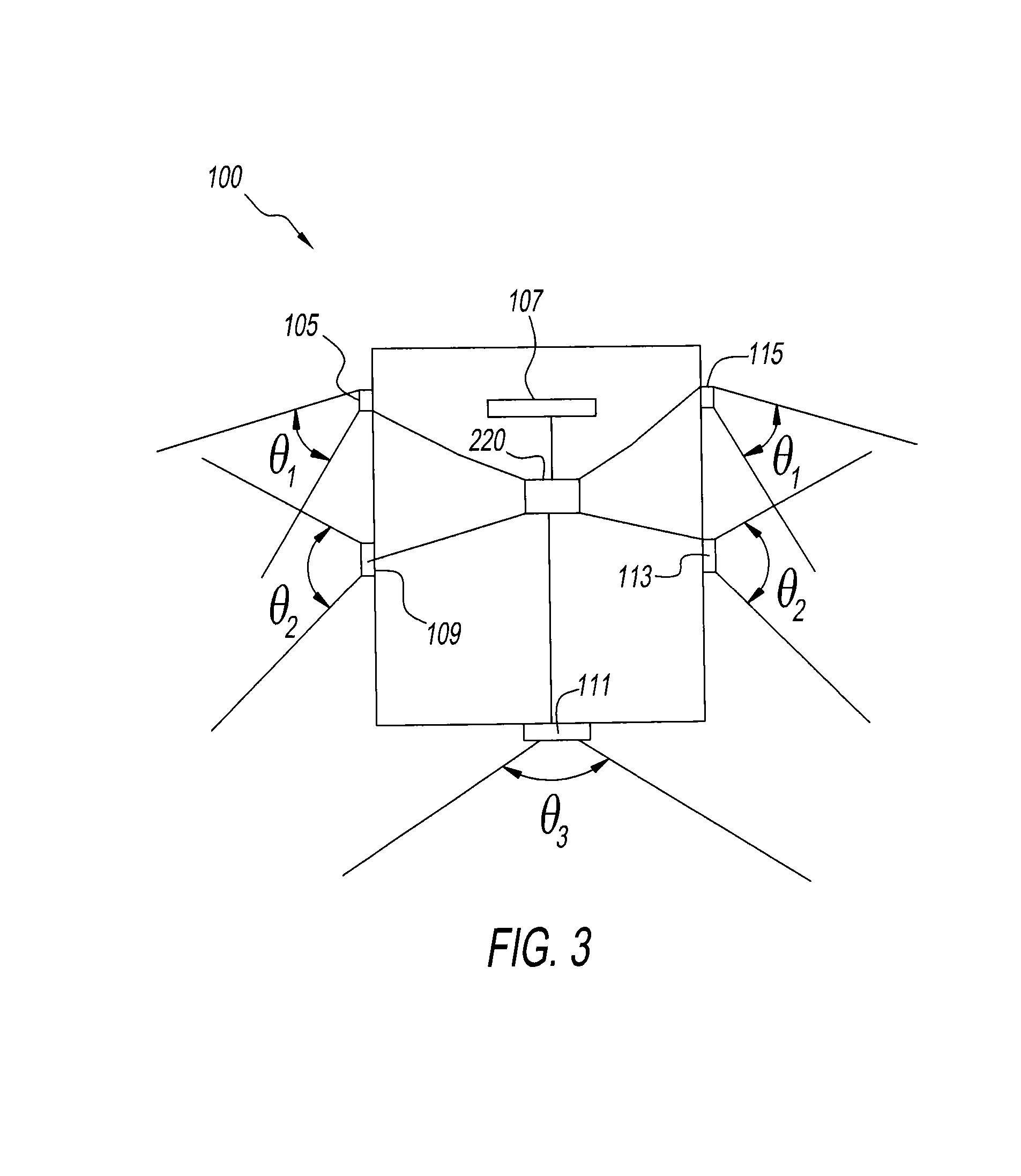
[0027]FIG. 1 shows an automobile 100 that includes a side view mirror 101. While the automobile 100 is shown as a pickup truck, it may also be a passenger sedan, SUV, tractor trailer, or other motorized vehicle. Integrated with the side view mirror 101 is a blind spot camera 105 (a digital video and / or digital still camera). A more detailed description of this configuration will be provided with reference to FIG. 2.

[0028]The system of FIG. 1 also includes a rear view mirror and display 107 that incorporates into a rear view mirror a display apparatus (as will be discussed in more detail with respect to FIG. 8). The display presents an indication (e.g., an illuminated LED) of a detected vehicle(s) around ...


PUM


Abstract

A blind-spot detection and collision avoidance system and method employ a blind-spot camera located between a side-view mirror and an automobile body. A rear view mirror has an integrated display that displays an indication of objects detected in blind spots. Side and rear view cameras are also included and images captured by these cameras are used to track objects as they are moved about the perimeter of the driver's automobile. Additional sensors are used to detect when the automobile is expected to change lanes so the collision avoidance system may be activated.

Description

GRANT OF NON-EXCLUSIVE RIGHT[0001]This application was prepared with financial support from the Saudi Arabian Cultural Mission, and in consideration therefore, the present inventor has granted the Kingdom of Saudi Arabia a non-exclusive right to practice the present invention.BACKGROUND[0002]1. Field of the Disclosure[0003]Embodiments described herein relate generally to a system and method for minimizing hazards of blind spots while driving. More particularly the embodiments described relate to a system and a method that can assist a driver in being made aware of other automobiles near the driver's automobile, which may not be visible in the driver's rear view and side view mirrors.[0004]2. Description of the Background[0005]Most automobiles are equipped with a passenger-side-view mirror, a driver-side-view mirror, and a rear-view mirror. These mirrors are used by the driver to identify vehicles that are located near the driver's automobile and assist the driver when the driver cha...

Claims


Application Information

Patent Timeline
IPC IPC(8): H04N7/18
Inventor ASSAF, MUSAID A.
Owner ASSAF MUSAID A
Learn More