Deposition apparatus and method of depositing thin film using the same

a technology of deposition apparatus and thin film, which is applied in the direction of chemical vapor deposition coating, coating, plasma technique, etc., can solve the problem of parasitic plasma formation in the enclosure of an external chamber

Active Publication Date: 2014-03-13
ASM IP HLDG BV
View PDF2 Cites 243 Cited by
  • Summary
  • Abstract
  • Description
  • Claims
  • Application Information

AI Technical Summary

Benefits of technology

[0007]The present invention has been made in an effort to provide a deposition apparatus and a method of depositing a thin film using the same having advantages of performing a stable process by generating plasma only within a reactor, thus preventing parasitic plasma from being generated in an external chamber, even if high RF power is supplied to the reactor.
[0011]According to an exemplary embodiment of the present invention, by maintaining pressure of an external chamber at a level that is slightly lower than pressure of a reaction space during a process by supplying a charge gas to an external chamber space between the reaction space and an outer wall, parasitic plasma can be prevented from being generated within the external chamber. Further, when loading or unloading a substrate, a charge gas of the external chamber can be prevented from flowing backward to the reaction space, and by supplying nitrogen gas as a charge gas, even if high plasma power is supplied, parasitic plasma can be effectively prevented from being generated in the external chamber.

Problems solved by technology

However, in the conventional dual reactor structure, as shown in FIG. 1, when plasma is formed within a reaction space while high radio frequency (RF) power is supplied to an internal reactor, parasitic plasma may be formed in an external chamber enclosing the internal reactor.

Method used


Image

  • Deposition apparatus and method of depositing thin film using the same
  • Deposition apparatus and method of depositing thin film using the same
  • Deposition apparatus and method of depositing thin film using the same

Examples


Embodiment Construction

[0015]The present invention will be described more fully hereinafter with reference to the accompanying drawings, in which exemplary embodiments of the invention are shown. As those skilled in the art would realize, the described embodiments may be modified in various different ways, all without departing from the spirit or scope of the present invention.

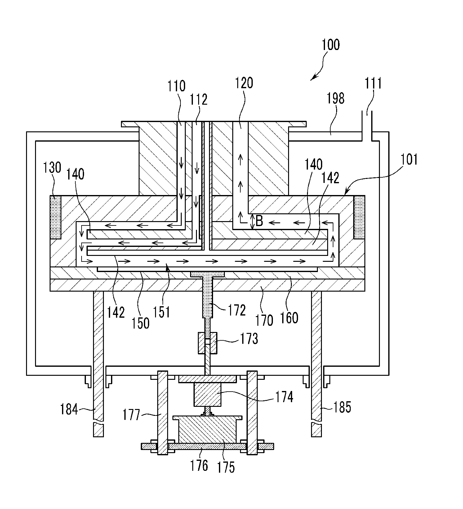
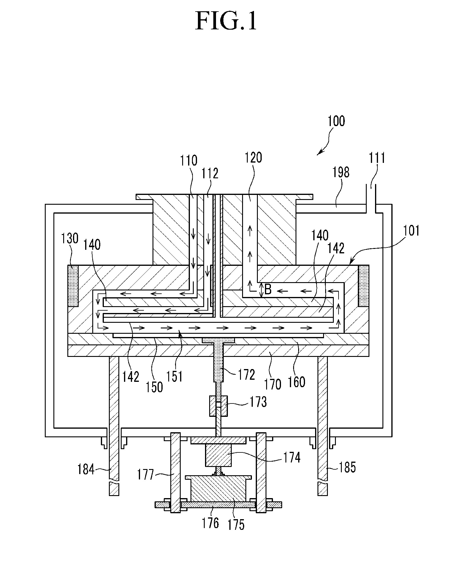
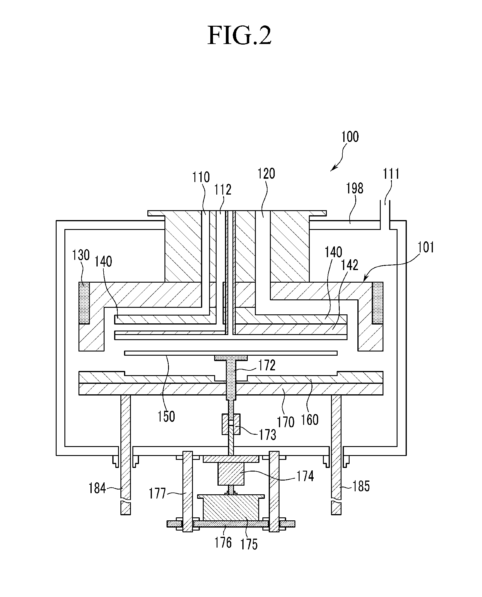
[0016]Hereinafter, a deposition apparatus and a deposition method using the same according to various exemplary embodiments of the present invention will be described with reference to FIGS. 1 and 2. FIGS. 1 and 2 are cross-sectional views illustrating a deposition apparatus according to an exemplary embodiment of the present invention. Specifically, FIG. 1 illustrates a cross-sectional view of a deposition apparatus when depositing a thin film and FIG. 2 illustrates a cross-sectional view of a deposition apparatus between thin film deposition processes.

[0017]Referring to FIGS. 1 and 2, a deposition apparatus 100 according to an exe...


PUM

PropertyMeasurementUnit
pressureaaaaaaaaaa
pressureaaaaaaaaaa
pressureaaaaaaaaaa

Abstract

A deposition apparatus and a method of depositing a thin film using the same are provided. By maintaining pressure of an external chamber between a reaction space and an outer wall slightly lower than pressure of the reaction space by supplying a charge gas to an external chamber of a space between the reaction space and an outer wall, parasitic plasma can be prevented from being generated within the external chamber. When loading or unloading a substrate, a charge gas of the external chamber can be prevented from flowing backward to the reaction space, and by supplying nitrogen gas as a charge gas, even if high plasma power is supplied, parasitic plasma can be effectively prevented from being generated in the external chamber.

Description

CROSS-REFERENCE TO RELATED APPLICATION[0001]This application claims priority to and the benefit of Korean Patent Application No. 10-2012-0100440 filed in the Korean Intellectual Property Office on Sep. 11, 2012, the entire contents of which are incorporated herein by reference.BACKGROUND OF THE INVENTION[0002](a) Field of the Invention[0003]The present invention relates to a deposition apparatus and a method of depositing a thin film using the same.[0004](b) Description of the Related Art[0005]In deposition apparatuses, in particular a deposition apparatus that can perform a plasma process, when plasma power is supplied to a reaction space, plasma is formed within the reaction space. However, in the conventional dual reactor structure, as shown in FIG. 1, when plasma is formed within a reaction space while high radio frequency (RF) power is supplied to an internal reactor, parasitic plasma may be formed in an external chamber enclosing the internal reactor. A potential of a reactor ...

Claims


Application Information

Patent Timeline
Patent Type & Authority Applications(United States)
IPC IPC(8): C23C16/50
CPCC23C16/50H01L21/205
Inventor KIM, KI JONG
Owner ASM IP HLDG BV
Why Eureka
Try Eureka