Pulley device, turning machine fitted with such a device and method of mounting such a device on a turning machine

Inactive Publication Date: 2014-03-13
AB SKF
View PDF61 Cites 0 Cited by
  • Summary
  • Abstract
  • Description
  • Claims
  • Application Information

AI Technical Summary

Benefits of technology

[0045]Thanks to the invention, the bearing, the axial retention means, the pulley, the torque transmission means and the torque limitation means form an integral assembly and can be transported from the production sites to an assembly site of a turning machine, thus simplifying the component management, reducing the

Problems solved by technology

Thus there are no means of retention to b

Method used


Image

  • Pulley device, turning machine fitted with such a device and method of mounting such a device on a turning machine
  • Pulley device, turning machine fitted with such a device and method of mounting such a device on a turning machine
  • Pulley device, turning machine fitted with such a device and method of mounting such a device on a turning machine

Examples


Example

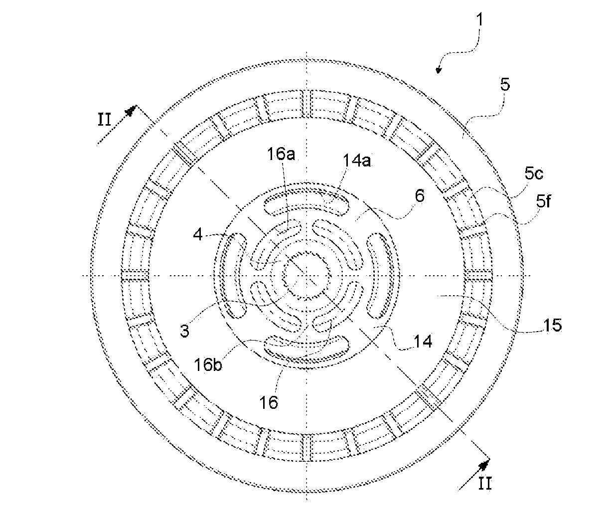
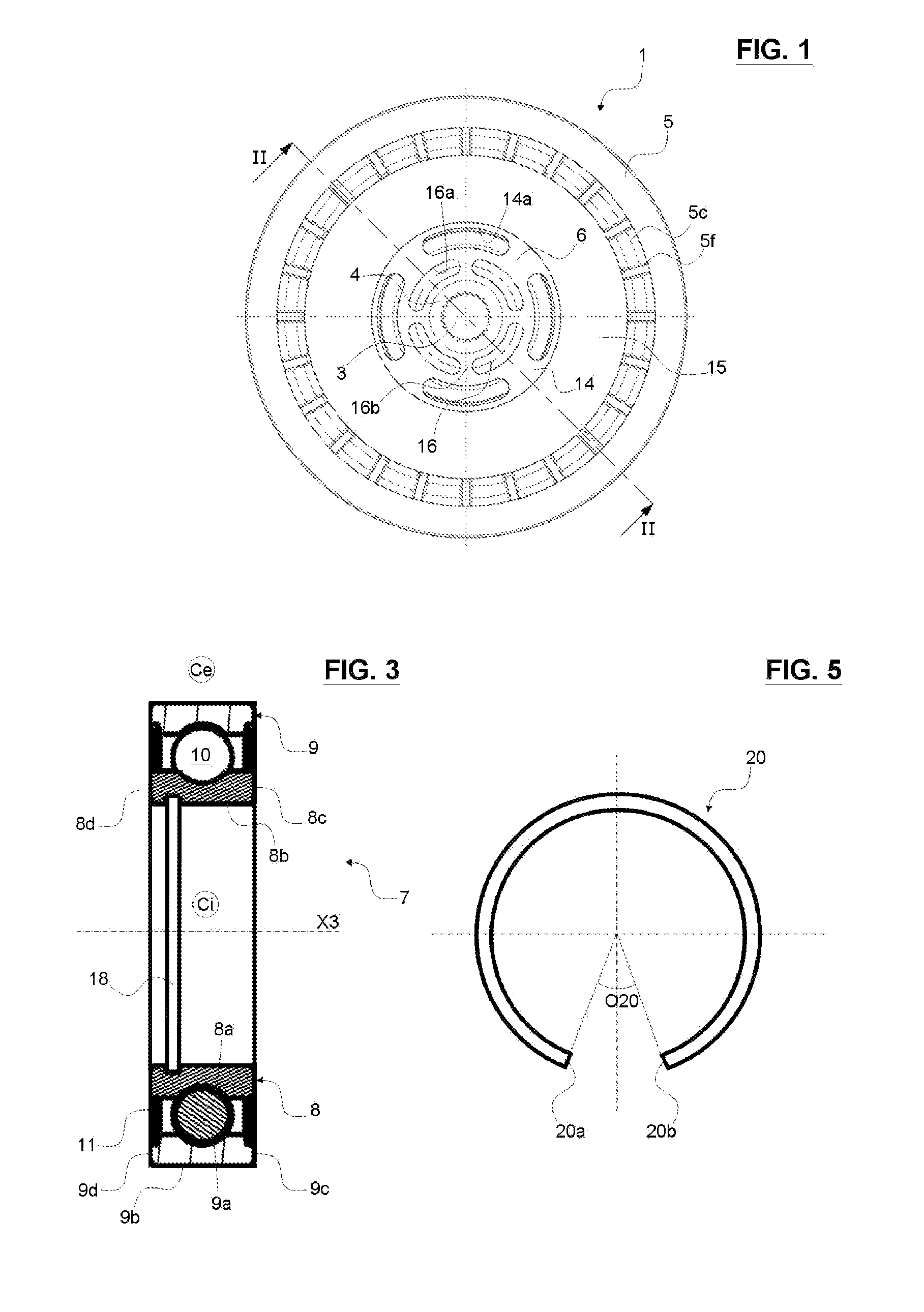
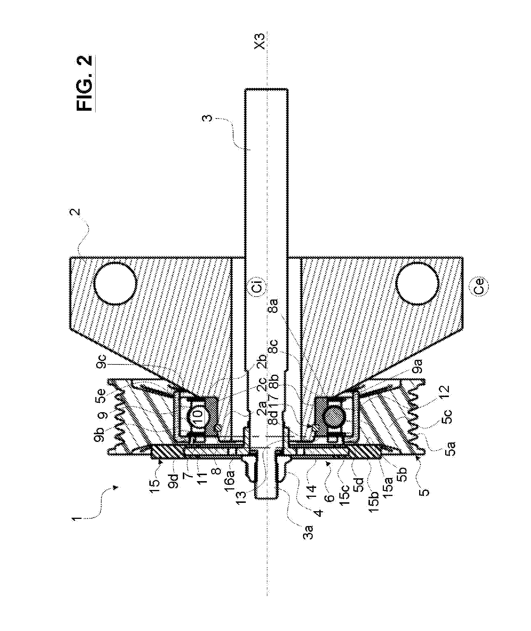
[0053]According to FIGS. 1 and 2, a pulley device 1 is mounted in a compressor comprising a non-rotating housing 2 and a transmission shaft 3 with rotation axis X3. The transmission shaft 3 comprises a threaded portion 3a intended to cooperate with a nut 4. The housing 2 comprises a hollow shaft 2a coaxial with the transmission shaft 3.

[0054]Then, to facilitate spatial referencing of the pulley device, an inside Ci is defined corresponding to the main axis X3, and an outside Ce opposite the axis X3 through the pulley device 1.

[0055]Furthermore the adjectives “axial” and “radial” and the adverb “axially” are defined in relation to the central axis X3 of the pulley device 1. Thus an axial portion or part is parallel to axis X3, while a radial portion or part is perpendicular to this axis and surrounds it. A surface is called axial when it extends perpendicular to axis X3 and radial when it extends perpendicular to a normal to this axis. For example a radial portion is provided with an...


PUM

PropertyMeasurementUnit
Timeaaaaaaaaaa
Torqueaaaaaaaaaa

Abstract

The invention concerns a pulley device (1) including a pulley (5), a torque transmission means (6) intended to be mounted between the pulley (5) and a transmission shaft (3) of a turning machine, and torque limitation means (16) intended to be mounted between the pulley (5) and the transmission shaft (3). The pulley device also includes at least one bearing (7) intended to be mounted on a non-rotating housing (2) of the turning machine and provided with an inner race (8) with a bore (8b), through which the inner race (8) is intended to be mounted on the housing (2), an outer race (9) and at least one row of rolling elements (10). According to the invention, the pulley device (1) provides axial retention means (17) arranged exclusively radially between the bore (8b) of the inner race (8) and the housing (2).

Description

CROSS-REFERENCE TO RELATED APPLICATIONS[0001]This application claims priority to French Patent Application 12 / 03027, filed Nov. 12, 2012, which is herein fully incorporated by reference.FIELD OF THE INVENTION[0002]The present invention concerns the field of devices for transmitting torque between a drive pulley device and a shaft driven by the pulley. A torque transmission device of this type may be used in particular in air conditioning compressors such as those mounted in automotive vehicles.BACKGROUND OF THE INVENTION[0003]In general, a drive pulley device comprises a pulley linked to a drive belt, at least one bearing between the pulley and a non-rotating housing of a turning machine, and a means for transmitting torque between the pulley and a rotating shaft of the turning machine.[0004]To remedy the harmful effects of acyclisms or sudden decelerations of the motor, which are transmitted to the pulley by a drive belt, it is known for example from JP-B-4015072 to incorporate tor...

Claims


Application Information

Patent Timeline
IPC IPC(8): F16H55/36
CPCF16H55/36F02B67/06F16H35/10F16H2055/366F16C19/06F16C35/063F16C2361/63Y10T29/49455
Inventor BERRUET, NICOLASCHAMBONNEAU, CHARLESVIAULT, SAMUEL
Owner AB SKF
Why Eureka
Try Eureka