

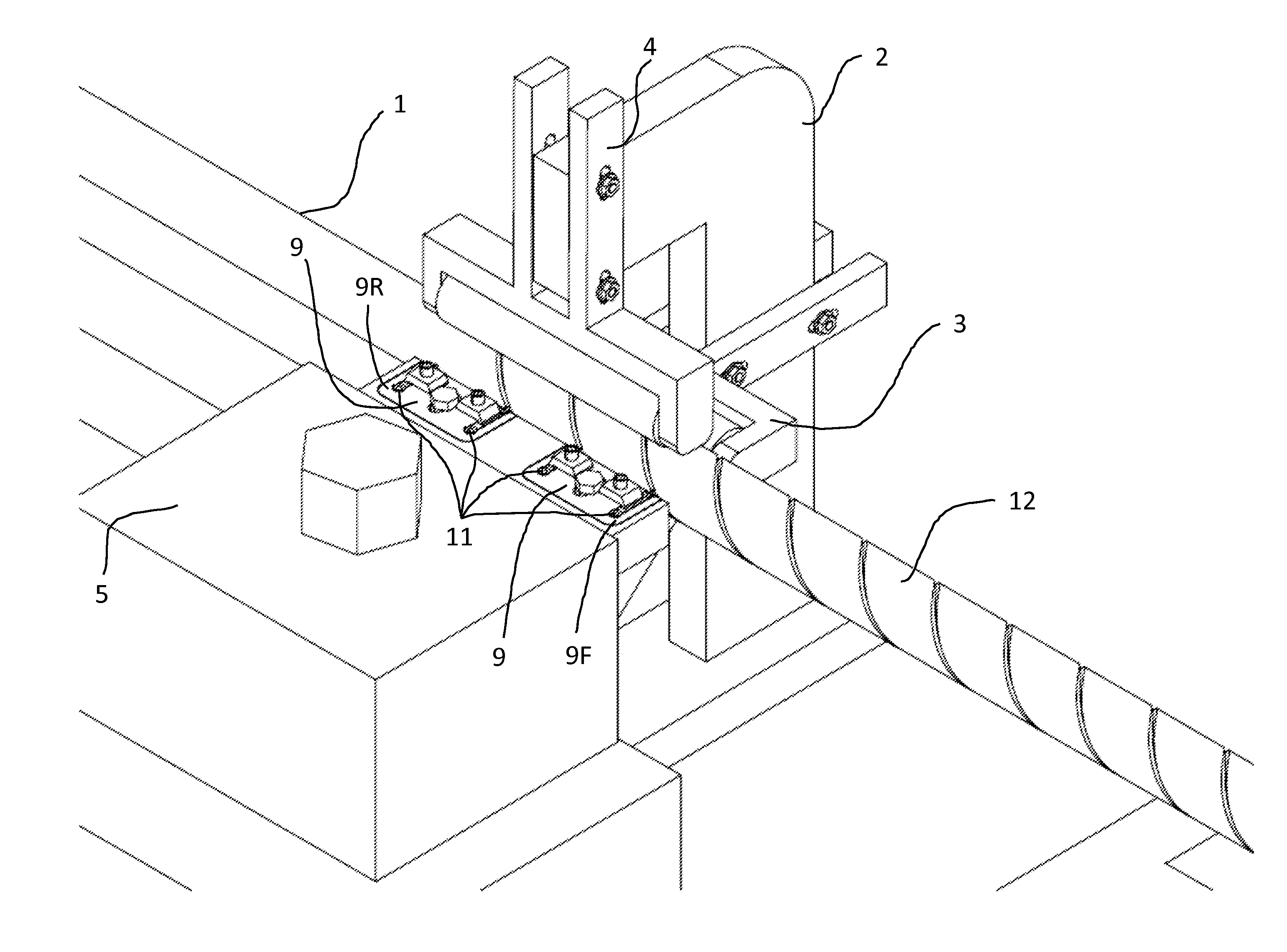
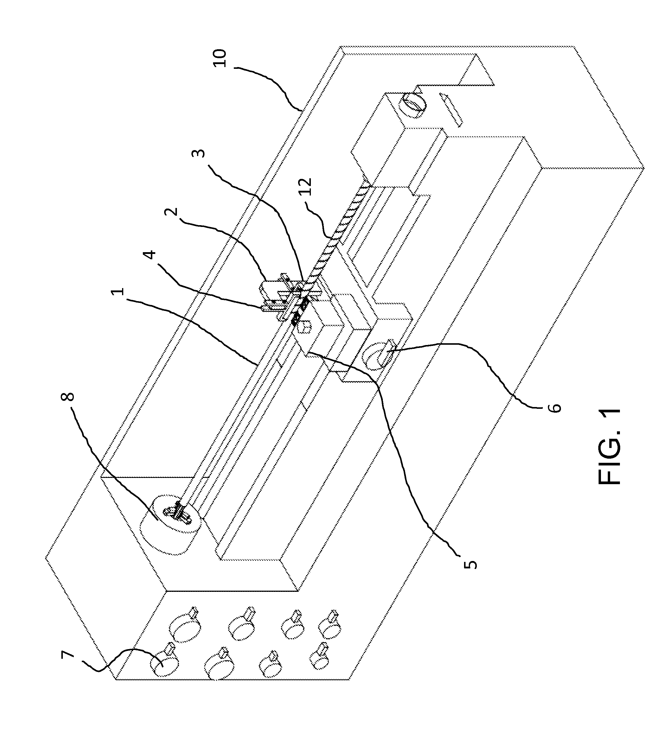
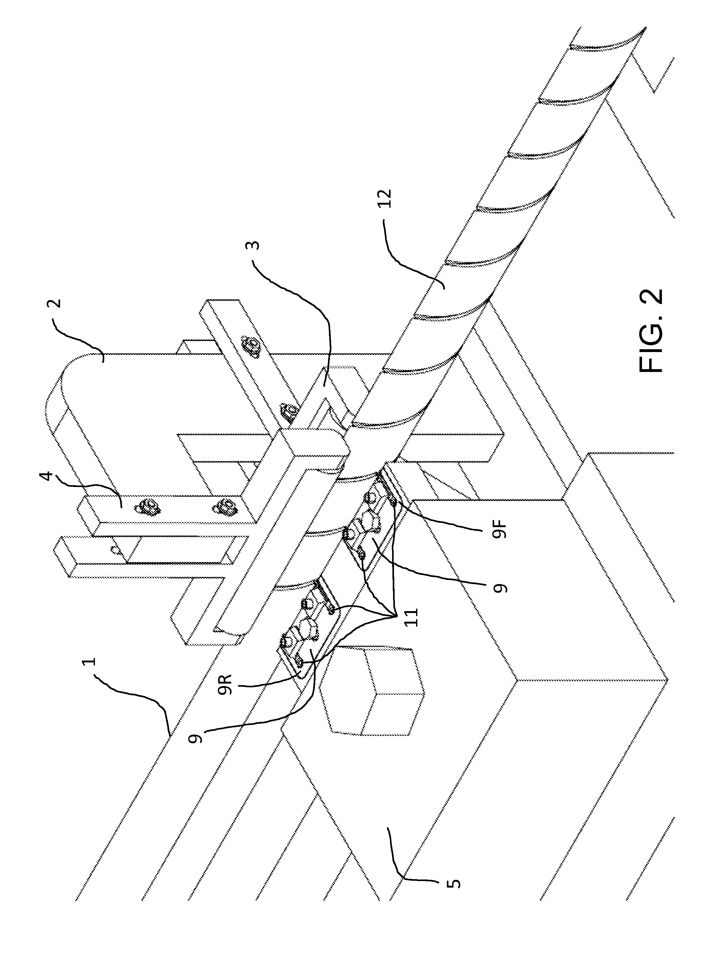
Method and apparatus for cutting one or more grooves in a cylindrical element
a technology of cylindrical elements and grooves, applied in the direction of manufacturing tools, door/window protective devices, suspension devices, etc., can solve the problems of time-consuming and complicated methods of forming or machining grooves, and achieve the effect of reducing tool changes and improving precision of groove alignmen
- Summary
- Abstract
- Description
- Claims
- Application Information
AI Technical Summary
Benefits of technology
Problems solved by technology
Method used
Image

Examples
embodiment 1
[0053]Embodiments of the invention are directed to a method and apparatus for cutting one or more grooves into an outer surface of a cylindrical element. A specific embodiment, which can be referred to as Embodiment 1, involves:
[0054]rotating a cylindrical element about a longitudinal axis of the cylindrical element;
[0055]where, while rotating the cylindrical element about the longitudinal axis, further incorporating:
[0056]moving a rough cutter and the rotating cylindrical element with respect to each other in a direction parallel to the longitudinal axis, where the rough cutter moves from a rough start position to a rough end position, wherein the rough start position has a rough axial start position along a length of the cylindrical element and a rough rotational start position about the longitudinal axis, where the rough end position has a rough axial end position along a length of the cylindrical element and a rough rotational end position about the longitudinal axis; and
[0057]m...
second embodiment
[0063]In a specific embodiment, which can be referred to as the second embodiment, wherein the rough rotational end position is the same as the rough rotational start position, wherein the finish rotational end position is the same as the finish rotational start position, wherein the finish rotational start position is the same as the rough rotational start position, where while moving the rough cutter from the rough start position to the rough end position, the rough cutter is maintained at the rough rotational start position, where while moving the finish cutter from the finish start position to the finish end position, the finish cutter is maintained at the finish rotational start position, where rotating the cylindrical element comprises rotating the cylindrical element at a constant speed of rotation, where moving the rough cutter from the rough start position to the rough end position comprises moving the rough cutter from the rough start position to the rough end position at ...
fourth embodiment
[0070]In a further specific embodiment, which can be referred to as the fourth embodiment, incorporating the limitations of Embodiment three, the second finish axial start position is axially separated from the second rough axial start position by m leads, where m is an integer having a value of 1 or greater. In this way the second finish cutter follows in the groove started by the second rough cutter. In a specific embodiment, m=1.
[0071]In a further specific embodiment, which can be referred to as embodiment five, incorporating the limitations of Embodiment four, where the second rough axial start position is axially separated from the finish axial start position by (p+½) leads, where p is an integer having a value of zero or greater, where p=0.
[0072]In a further specific embodiment, which can be referred to as Embodiment six, incorporating the limitations of Embodiment 1, while rotating the cylindrical element about the longitudinal axis, further incorporating:
[0073]moving a secon...
PUM
| Property | Measurement | Unit |
|---|---|---|
| Angle | aaaaa | aaaaa |
| Speed | aaaaa | aaaaa |
| Distance | aaaaa | aaaaa |
Abstract
Description
Claims
Application Information