
Mechanical clamping cut-off tool

A technology for cutting off knives and machine clips, which is applied in the attachments of tool holders, tools for lathes, turning equipment, etc., can solve the problems of uneven cutting feed, the cutting edge cannot be very wide, and the smoothness is affected, and the sharpening of the knife can be achieved. The effect of time reduction, labor intensity reduction, and widespread promotion of value

Inactive Publication Date: 2014-03-05
HARBIN BEARING GROUP CORP
View PDF11 Cites 0 Cited by
  • Summary
  • Abstract
  • Description
  • Claims
  • Application Information

AI Technical Summary

Problems solved by technology

The cutting edge should not be very wide. If it is too wide, the turning tool will vibrate, or even break the tool, and the corresponding cutting surface will also have vibration lines on the surface, which will affect the finish; Uniform, which increases the chance of vibration

Method used


Image

  • Mechanical clamping cut-off tool

Examples


Embodiment Construction

[0013] Below in conjunction with accompanying drawing and specific embodiment the present invention will be further described:

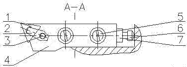
[0014] combine figure 1 , this embodiment includes a blade 1, a pressure plate 2, a position clamping screw 3, a cutter body 4, a position positioning screw 5, a length positioning screw 6 and a length locking nut 7, and the blade 1 is fixed on the cutter body 4 through the pressure plate 2, The pressing plate 2 is installed on the machine tool through the position clamping screw 3 , the length positioning screw 6 is arranged on the rear end of the cutter body 4 , and the length locking nut 7 is arranged on the length positioning screw 6 . The blade 1 is composed of three equal triangular cutting edges, which are installed on the front end of the cutter body 4 respectively. The position clamping screw 3 includes two screws arranged side by side, and a nut is installed on the screw.


PUM


Abstract

The invention provides a mechanical clamping cut-off tool which comprises a blade, a pressure plate, location clamping screws, a tool body, location positioning screws, a length positioning screw and a length locking nut. The blade is fixed onto the tool body by the aid of the pressure plate, the pressure plate is mounted on a machine tool via the location clamping screws, the length positioning screw is arranged at the rear end of the tool body 4, and the length locking nut is arranged on the length positioning screw. The mechanical clamping cut-off tool has the advantages that shortcomings of a manual cut-off tool sharpening mode can be overcome, raw materials can be saved, the tool changing and sharpening time can be shortened, the labor intensity can be greatly reduced, and the like.

Description

technical field [0001] The invention relates to the field of cutting tool design, in particular to a machine clip cutting knife. Background technique [0002] The cutting process is often encountered in the processing of bearing rings. From the perspective of saving steel, cutting knives are made narrower and less rigid than ordinary knives. The cutting knife not only bears the radial force, but also bears the axial force. If the angle of the knife sharpening is unreasonable, it will affect the service life of the knife. When the steel is cut off, it is in a semi-closed state, it is difficult to remove chips, and it is difficult to achieve sufficient cooling of the tool. At present, manual sharpening of knives occupies a relatively large proportion, and manual sharpening requires operators to have a certain technical level, but the width of sharpened knives is difficult to unify. Although the width of the tool is too wide, it can improve the life of the tool, but it is a ...

Claims


Application Information

Patent Timeline
Patent Type & Authority Applications(China)
IPC IPC(8): B23B27/04
CPCB23B27/04
Inventor 刘艳敏刘莹袁新李征张庆秋刘英学张丽君王志新宋磊
Owner HARBIN BEARING GROUP CORP
Learn More