Solar module array pre-assembly method and apparatus

a solar module array and pre-assembly technology, applied in the direction of heat collector mounting/support, light and heating apparatus, furniture parts, etc., can solve the problems of installation costs that amount to around 25% of the overall cost of a solar parking shade installation, and the actual panel cost is often almost the actual cos

Inactive Publication Date: 2014-03-20
ENGIE SERVICES U S INC
View PDF31 Cites 11 Cited by
  • Summary
  • Abstract
  • Description
  • Claims
  • Application Information

AI Technical Summary

Problems solved by technology

Beyond the photo-electro voltaic cell technology itself are the problems of placement and support of the solar collector panels.
In prior known systems, installation costs amount to around 25% of the overall cost of a solar parking shade installation.
These installation cost includes the cost to place modules on a rack, wire the modules together and to a combiner box, bolt the modules in place, and place the support structure on a parking shade structure.
These costs often amount to almost the actual panel cost themselves due to the lack of ability to achieve assembly efficiency as well as the need in governmental markets to use union labor.
An additional deficiency in known methods / systems for solar canopy installation is that the size of solar modules used is limited to the size module a contractor can physically carry.
The installation process is also cumbersome and dangerous due to work on nonstandard sites and at an elevated height.

Method used


Image

  • Solar module array pre-assembly method and apparatus
  • Solar module array pre-assembly method and apparatus
  • Solar module array pre-assembly method and apparatus

Examples


Embodiment Construction

[0067]Other embodiments of the present invention and its individual components will become readily apparent to those skilled in the art from the foregoing detailed description. As will be realized, the invention is capable of other and different embodiments, and its several details are capable of modifications in various obvious respects, all without departing from the spirit and the scope of the present invention. Accordingly, the drawings and detailed description are to be regarded as illustrative in nature and not as restrictive. It is therefore not intended that the invention be limited except as indicated by the appended claims.

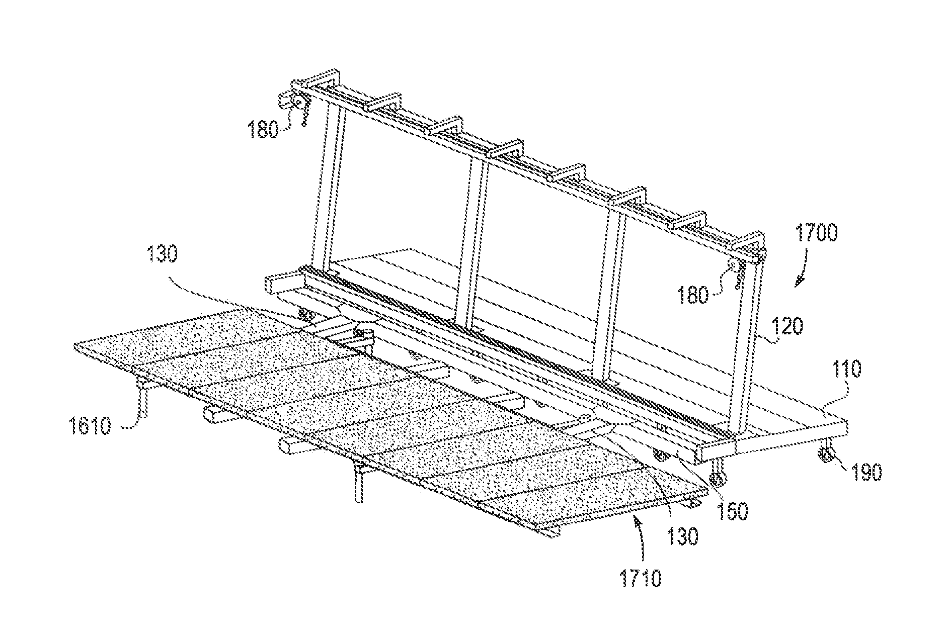
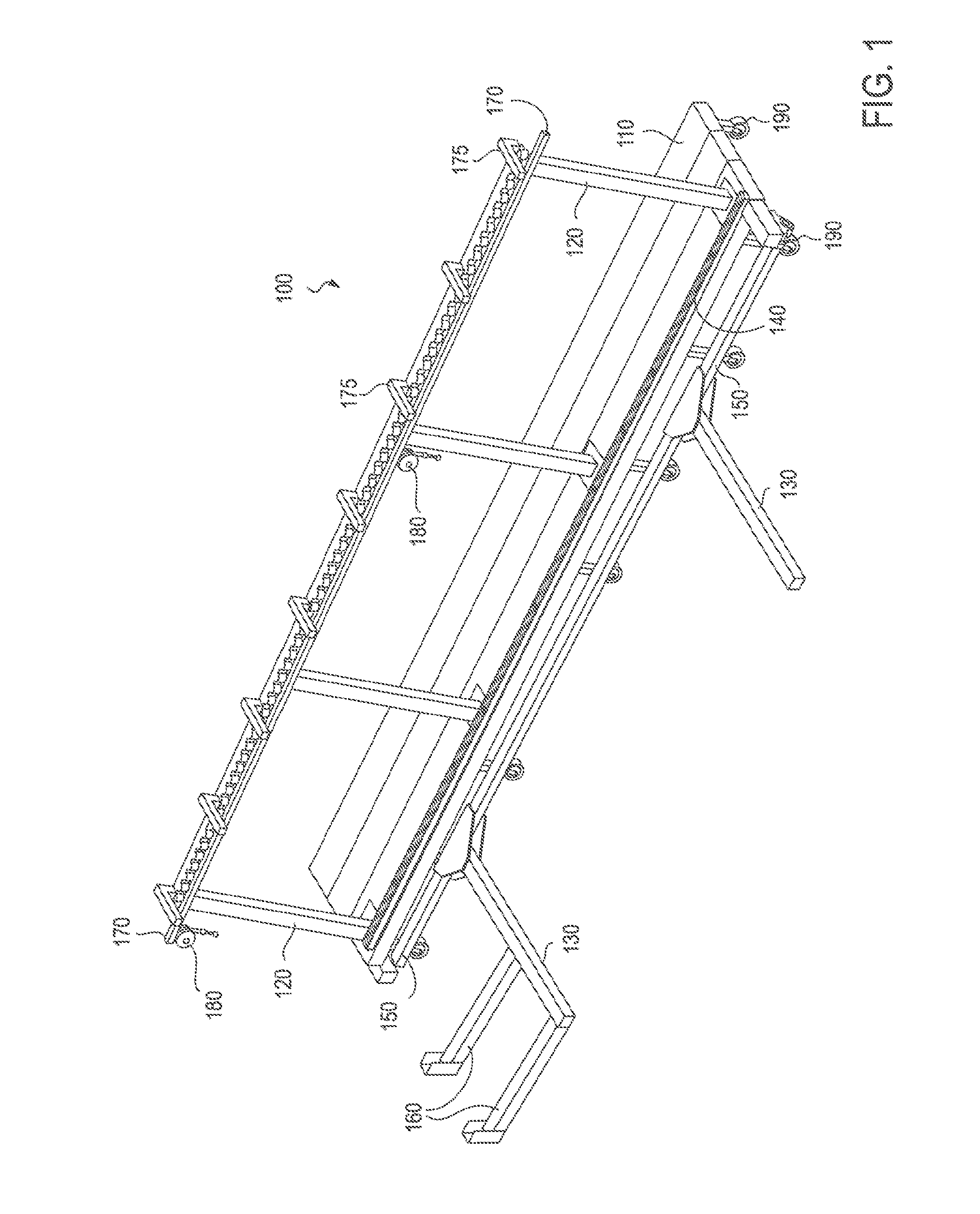
[0068]As used in this specification and claims, the “solar panel support channels” comprise “Z”-shaped sheet metal, also referred to as “Zee-channels” or “Z-channels”, “C”-shaped sheet metal, also referred to as “Cee-channels” or “c-channels”, or standard beams, bars, and other suitable support members.

[0069]FIG. 1 is a perspective view of one embodiment...


PUM


Abstract

The present invention is directed to an apparatus for stacking a plurality of solar module arrays each having a plurality of solar panels. The apparatus includes a lower portion disposed on top of a first solar panel support channel corresponding to a first solar module array, and an upper portion for supporting a second solar panel support channel corresponding to a second solar module array, wherein the second solar module array is stacked above the first solar module array.

Description

CROSS-REFERENCE TO RELATED APPLICATIONS[0001]This application is a continuation-in-part of pending U.S. patent application Ser. No. 13 / 112,314 filed on May 20, 2011, the contents of which are incorporated by reference in its entirety.COPYRIGHT NOTICE AND AUTHORIZATION[0002]This patent document contains material which is subject to copyright protection.[0003]© Copyright 2010-2013. Chevron Energy Solutions Company, a division of Chevron U.S.A. Inc. All rights reserved.[0004]A portion of the disclosure of this patent document contains material which is subject to copyright protection. The copyright owner has no objection to the facsimile reproduction by anyone of the patent document or the patent disclosure, as it appears in the Patent and Trademark Office patent file or records, but otherwise reserves all copyright rights whatsoever.FIELD OF THE INVENTION[0005]This invention relates an apparatus and method for pre-assembly of certain components of a solar canopy.BACKGROUND OF THE INVE...

Claims


Application Information

Patent Timeline
Patent Type & Authority Applications(United States)
IPC IPC(8): H01L31/042
CPCH01L31/0422B65G49/063B65G49/067B65G49/068H01L31/02B60P3/002B65G49/062F24S2025/013F24S2025/014F24S25/10F24S25/60F24S25/37Y02E10/47Y02E10/50H02S30/10
Inventor POTTER, DAVID STERLING
Owner ENGIE SERVICES U S INC
Why Eureka
Try Eureka