Method and apparatus for linked horizontal drapery panels having varying characteristics to be moved independently by a common drive system

a technology of horizontal drapery panels and drive systems, applied in the direction of curtain suspension devices, door/window protective devices, shutters/movable grilles, etc., can solve the problems of increasing assembly costs and adding complexity to the assembly

a technology of horizontal drapery panels and drive systems, applied in the direction of curtain suspension devices, door/window protective devices, shutters/movable grilles, etc., can solve the problems of increasing assembly costs and adding complexity to the assembly

US20140076505A1Inactive Publication Date: 2014-03-20QMOTION

Image

  • Method and apparatus for linked horizontal drapery panels having varying characteristics to be moved independently by a common drive system
  • Method and apparatus for linked horizontal drapery panels having varying characteristics to be moved independently by a common drive system
  • Method and apparatus for linked horizontal drapery panels having varying characteristics to be moved independently by a common drive system

Examples


embodiment

Method and Apparatus for Linked Horizontal Drapery Panels Having Varying Characteristics to be Moved Independently by a Common Drive System

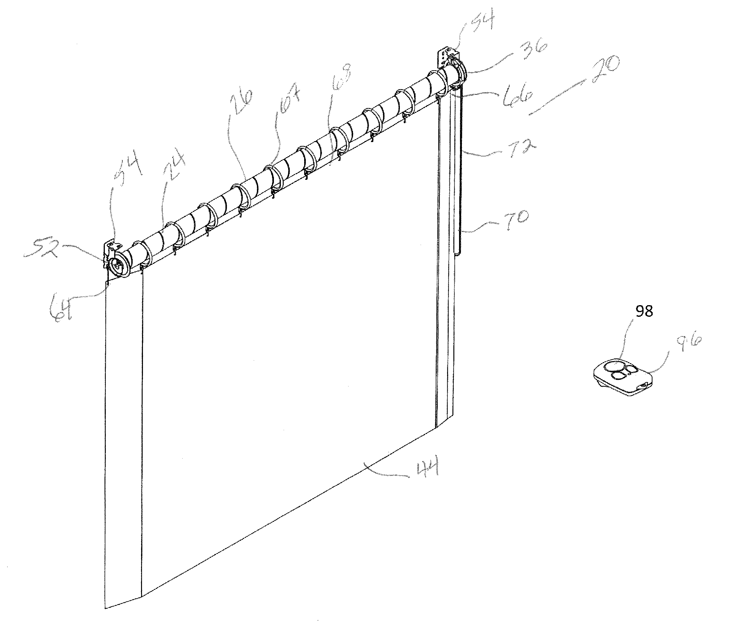
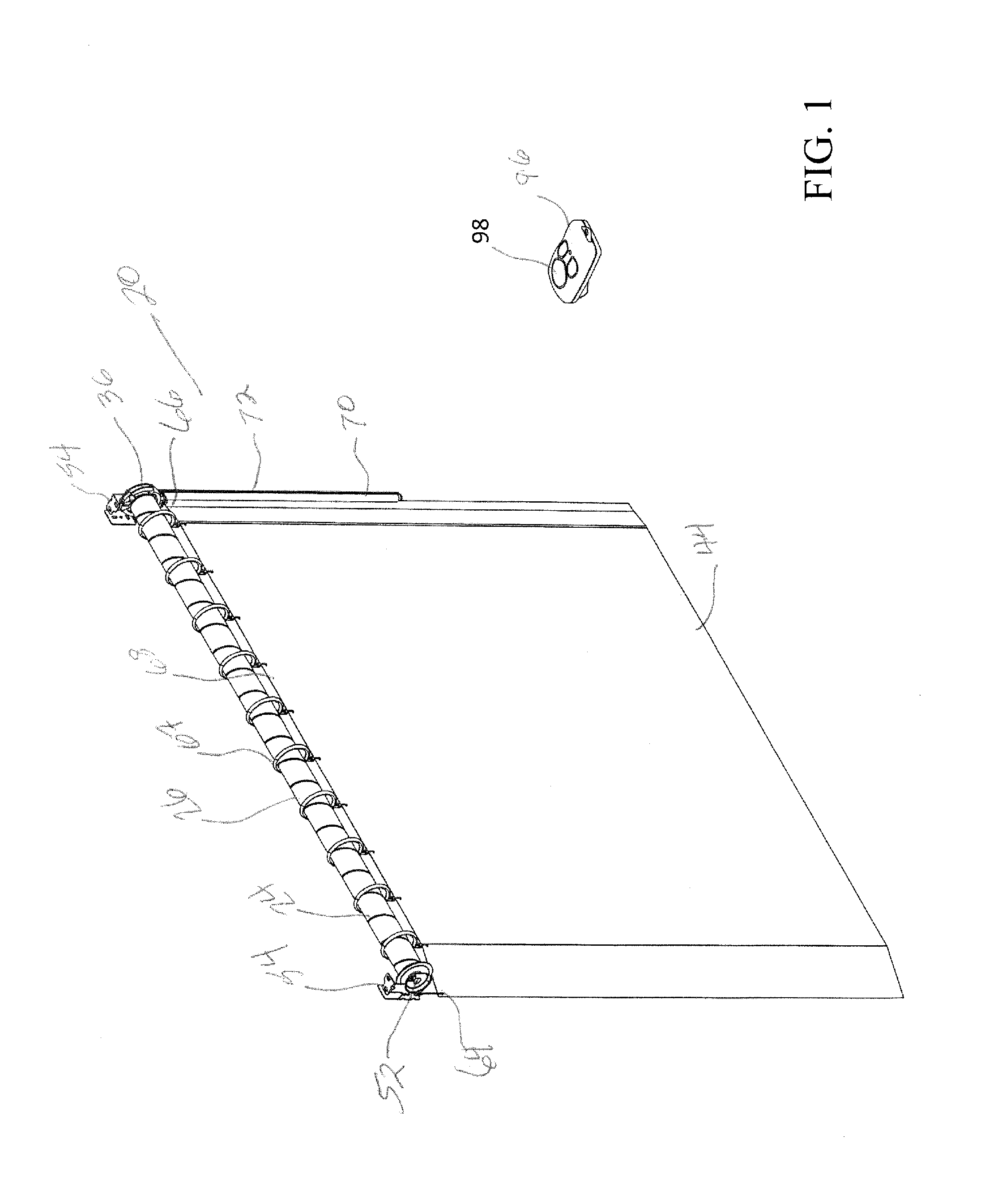
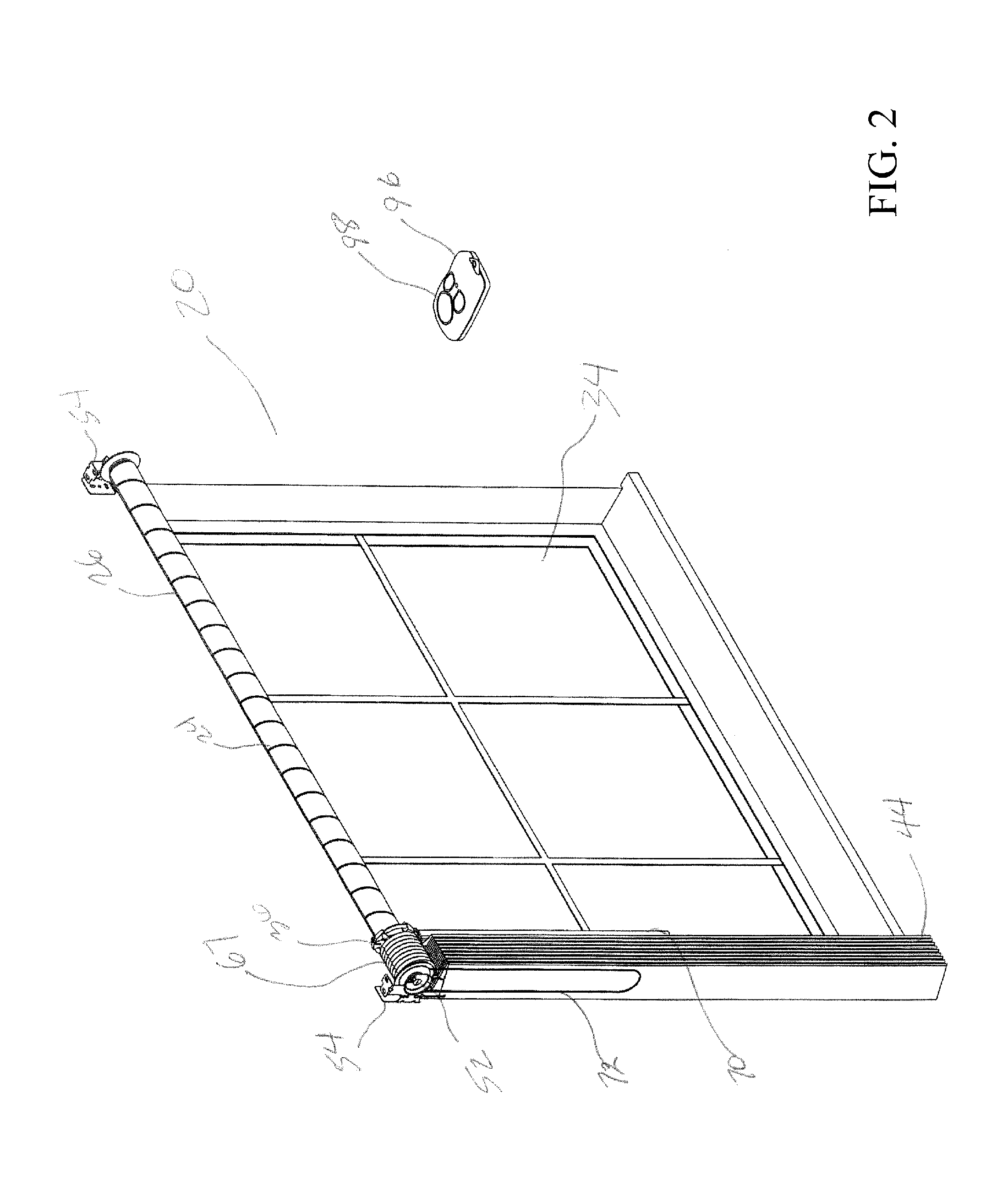
[0211]A system having two horizontal moving curtains or draperies made from dissimilar materials can display each of the two curtains individually, using a common drive system. The drive system can be operated manually by, for example, a pull cord or a draw rod, and can be motorized. In the embodiment, shown in FIGS. 64-77, the horizontal movement of the curtain or drapery is accomplished by one or more grooves, such as one or more helical grooves, formed on the outer surface of a rotating element, such as a roll shade tube, to move the curtain or drapery horizontally when the tube rotates. The drive element can also utilize a sleeve over a tube, such that the sleeve has the one or more grooves and rotating the tube rotates the sleeve. The sleeve and tube can be the same material or different materials. A sleeve made of non-metallic material over...


PUM

PropertyMeasurementUnit
outer diameteraaaaaaaaaa

Abstract

A curtain assembly comprises a rotatable drive element wherein at least one helical guide structure is formed on, or into, the outer surface of the drive element. A drive attachment element having a structure that communicates with the helical guide structure to move the drive attachment element axially along the drive element when the drive element is rotated. Specific embodiments incorporate either a manual or motor-driven rotation assembly for rotating the drive element. Further specific embodiments involve a helical guide structure that comprises a helical groove and a structure that comprises a tooth that engages with the helical groove. Further specific embodiments relate to a system with linked horizontal drapery panels having varying characteristics that are moved independently by a common drive system.

Description

CROSS-REFERENCE TO RELATED APPLICATION[0001]The present application claims the benefit of U.S. Patent Application Ser. No. 61 / 702,093, filed Sep. 17, 2012, which is hereby incorporated by reference herein in its entirety, including any figures, tables, or drawings.FIELD OF THE INVENTION[0002]Embodiments of the present invention relate generally to a window covering assembly used to cover windows. Specific embodiments of the invention relate to a window covering assembly with a rotatable drive element that has a structure formed into or on the outer surface of the rotatable drive element such that a window covering moves axially along the rotatable drive element when the rotatable drive element rotates. Further specific embodiments relate to a window covering assembly in which two different curtains are operated by the same rotating drive element such that the user is able to independently move each curtain. Further specific embodiments relate to a system with linked horizontal drape...

Claims


Application Information

Patent Timeline
20 Mar 2014
Publication
US20140076505A1
IPC
E06B9/40; A47H23/00
CPC
A47H23/00; E06B9/40; A47H1/02; A47H5/06; B23B3/00; B23B5/08; B23B29/26; B23Q1/766
Inventors
MULLET, WILLIS JAY; FOX, MICHAEL D.