
Branching Apparatus for Branching Pipes

Inactive Publication Date: 2014-03-20
JUNG BYOUNG YONG +3
View PDF5 Cites 3 Cited by
  • Summary
  • Abstract
  • Description
  • Claims
  • Application Information

AI Technical Summary

Benefits of technology

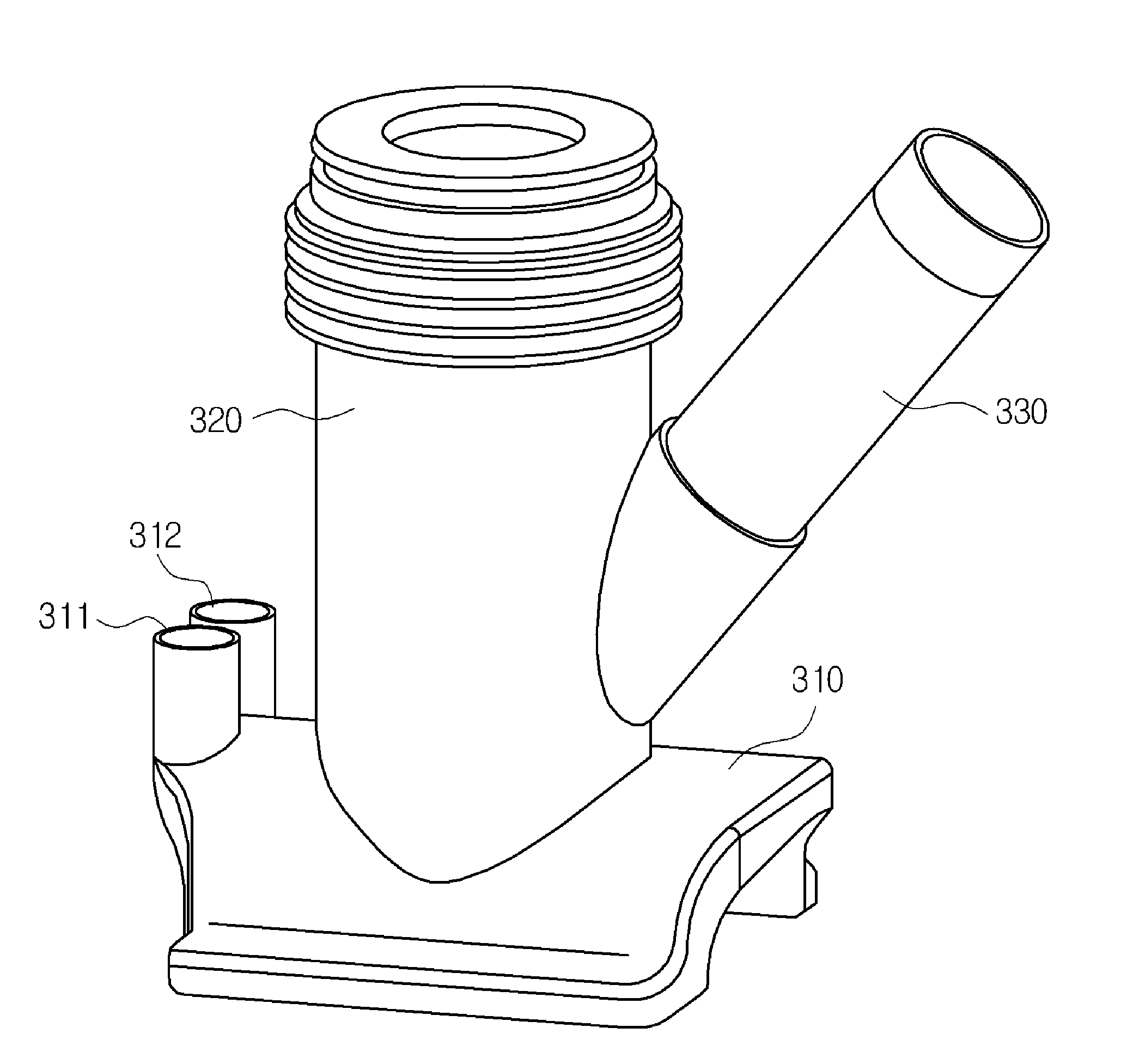
The present invention aims to solve problems in the prior art by providing a branching apparatus that minimizes energy loss, allows for easy installation of a trace wire, and ensures the wire is not bent. The apparatus includes two power supply terminals mounted on a saddle in the opposite direction of a branch connection part branched from a cylindrical body. This design makes it easy to connect the power supply. Additionally, the branch connection part is slantly mounted directly above the main pipe, which prevents bending of the trace wire and allows it to follow its exact length and position.

Problems solved by technology

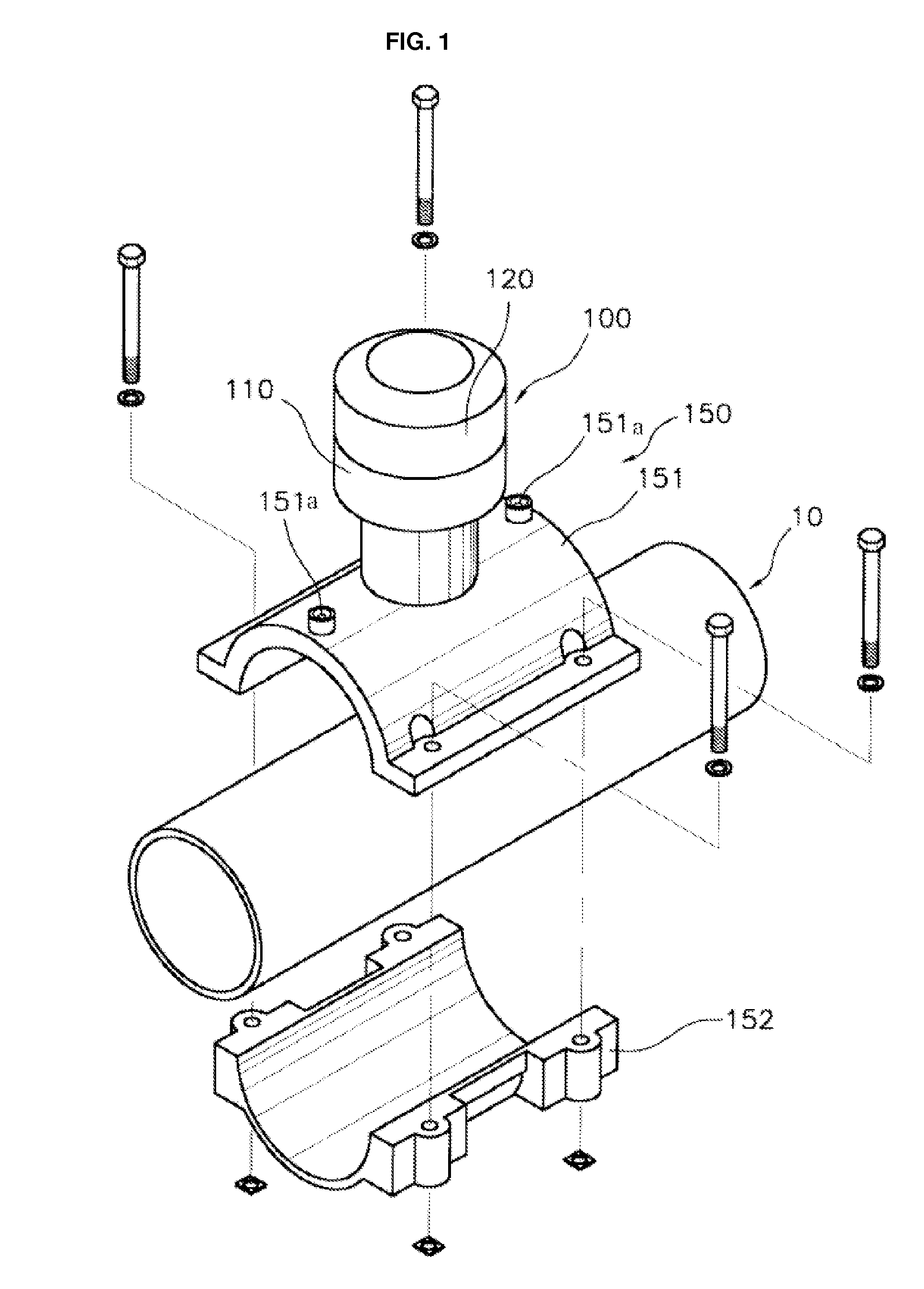
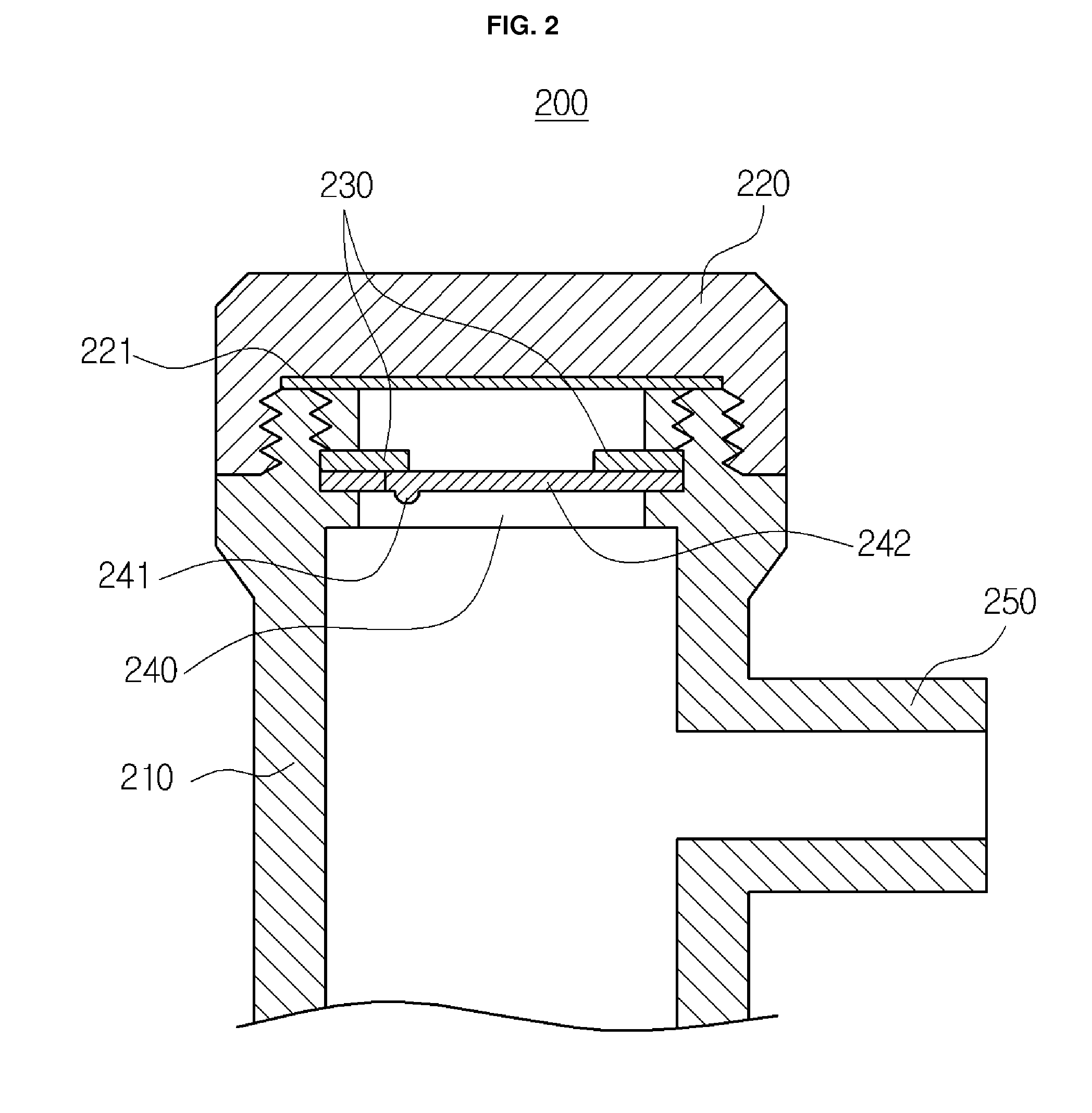
However, in the piping structure illustrated in FIG. 2, the trace wire is bent twice in order to be inserted into the main pipe 10 through the branch connection part 250, and hence, it is difficult that the trace wire exactly goes along the main pipe 10, or the trace wire may cause communication problems even though it is exactly inserted into the main pipe 10.
Moreover, as shown in FIG. 2, when the trace wire is bent vertically twice in a short flow passage where the main pipe 10 and the branch connection part 250 are connected, because a great resistance is formed in the flow passage, it causes a great loss of energy.

Method used


Image

  • Branching Apparatus for Branching Pipes
  • Branching Apparatus for Branching Pipes
  • Branching Apparatus for Branching Pipes

Examples


Embodiment Construction

[0021]Reference will be now made in detail to the preferred embodiment of the present invention with reference to the attached drawings.

[0022]FIG. 3 is a sectional view showing an installation state of a branching apparatus according to the present invention, and FIG. 4 is a perspective view showing a cover is not mounted on the branching apparatus according to the present invention.

[0023]The branching apparatus 300 illustrated in FIGS. 3 and 4 includes: a saddle 310 fused on an upper surface of a main pipe 301 in which a fluid, preferably, gas flows; a cylindrical body 320 extending upwardly from the saddle 310 and having a hollow portion communicating with an opening 302 of the main pipe 301; and a branch connection part 330 slantly branched from the cylindrical body 320 and keeping an angle (A) to a center line(C) of the main pipe 301.

[0024]An electric heating wire is mounted in a lower face of the saddle 310. The electric heating wire is heated by electricity flowing through two...


PUM

PropertyMeasurementUnit
Angleaaaaaaaaaa
Angleaaaaaaaaaa
Lengthaaaaaaaaaa

Abstract

The branching apparatus according to the present invention includes two power supply terminals mounted on a saddle in the opposite direction of a branch connection part branched from a cylindrical body, so that they are not overlapped with the branch connection part when an electric socket is connected to the power supply terminal, and hence, it provides easiness in work. Moreover, because the branch connection part is slantly mounted directly above the main pipe, a trace wire inserted into the branch connection part and the main pipe is not bent, and hence, the trace wire can trace exact length and position.

Description

REFERENCE TO RELATED APPLICATIONS[0001]This application claims the priority benefit of Korean Patent Application No. 1 0-201 2-01 04447 filed on Sep. 20, 2012, the entire contents of which are incorporated herein by reference.FIELD OF THE INVENTION[0002]The present invention relates to a branching apparatus for connecting a branch pipe from a main pipe in which a fluid flows or for installing auxiliary devices including a measuring device to the main pipe.BACKGROUND OF THE INVENTION[0003]In order to repair a main pipe in which a fluid, such as gas, flows, to install branch pipes, or to install auxiliary devices, various kinds of branching apparatuses fused to the main pipe have been studied. Korean Patent Laid-open No. 2003-0084283 (entitled “Socket for plugging pipes and pipe branching apparatus using the same) (hereinafter, called a ‘prior art’) discloses a socket and a branching apparatus for conveniently connecting a branch pipe with a device for conveniently repairing a main pi...

Claims


Application Information

Patent Timeline
IPC IPC(8): F16L41/06
CPCF16L41/06F16L41/004F16L41/12F16L47/26F16L41/02
Inventor JUNG, BYOUNG YONGDEASON, MICHAEL TROYSIN, YOUNG SUKKOKOSKI, BRADLEY ROBERT
Owner JUNG BYOUNG YONG
Learn More