Capacitor bank, laminated bus, and power supply apparatus

a power supply and capacitor technology, applied in the field of solid-state switched power supplies, can solve the problems of reducing the attainable net power density as installed, adding costs in design, manufacturing and operation, and reducing the attainable net power density

Inactive Publication Date: 2014-03-20
GENERAL ELECTRIC CO
View PDF20 Cites 69 Cited by
  • Summary
  • Abstract
  • Description
  • Claims
  • Application Information

AI Technical Summary

Benefits of technology

[0009]In embodiments, a capacitor bank includes a laminated bus bar having a high potential conductive layer and a low potential conductive layer disposed at opposing surfaces of an intervening insulation layer. The bank also includes a plurality of bus capacitors electrically connected to the laminated bus bar. The laminated bus bar and the bus capacitors have a combined inductance sufficiently low such that the bus capacitors are electrically connected effectively in parallel with the laminated bus bar.
[0010]In other embodiments, a power supply apparatus includes a laminated bus bar having a high potential conductive layer and a low potential conductive layer disposed in close proximity at opposing surfaces of an intervening insulation layer. The high potential conductive layer includes an array of high potential vias and the low potential conductive layer includes an array of low potential vias. The apparatus further includes plural bus capacitors each having a high potential terminal electrically connected to the high potential conductive layer and having a low potential terminal electrically connected to the low potential conductive layer of the bus bar, and plural power converters, each connected across one of the high potential vias and one of the low potential vias. The power converters have no commutating capacitors.

Problems solved by technology

As will be appreciated, these features add costs in design, manufacturing, and operation.
In operation, the capacitors cause each conventional power converter to occupy greater volume, and to dissipate more heat, than would otherwise be needed, thereby diminishing the attainable gross power density.
Heat dissipation from the capacitors also increases a parasitic load required for cooling the power converters, thereby reducing the attainable net power density as installed.
As such, the conventional power converters that include the capacitors have significant excess cost, have higher cooling requirements, and have lower gravimetric and volumetric net power density than would be desirable.

Method used


Image

  • Capacitor bank, laminated bus, and power supply apparatus
  • Capacitor bank, laminated bus, and power supply apparatus
  • Capacitor bank, laminated bus, and power supply apparatus

Examples


Embodiment Construction

[0018]Reference will be made below in detail to exemplary embodiments of the invention, examples of which are illustrated in the accompanying drawings. Wherever possible, the same reference characters used throughout the drawings refer to the same or like parts, without duplicative description. Although exemplary embodiments of the present invention are described with respect to an AC power supply, embodiments of the invention also are applicable for use with power supplies, generally.

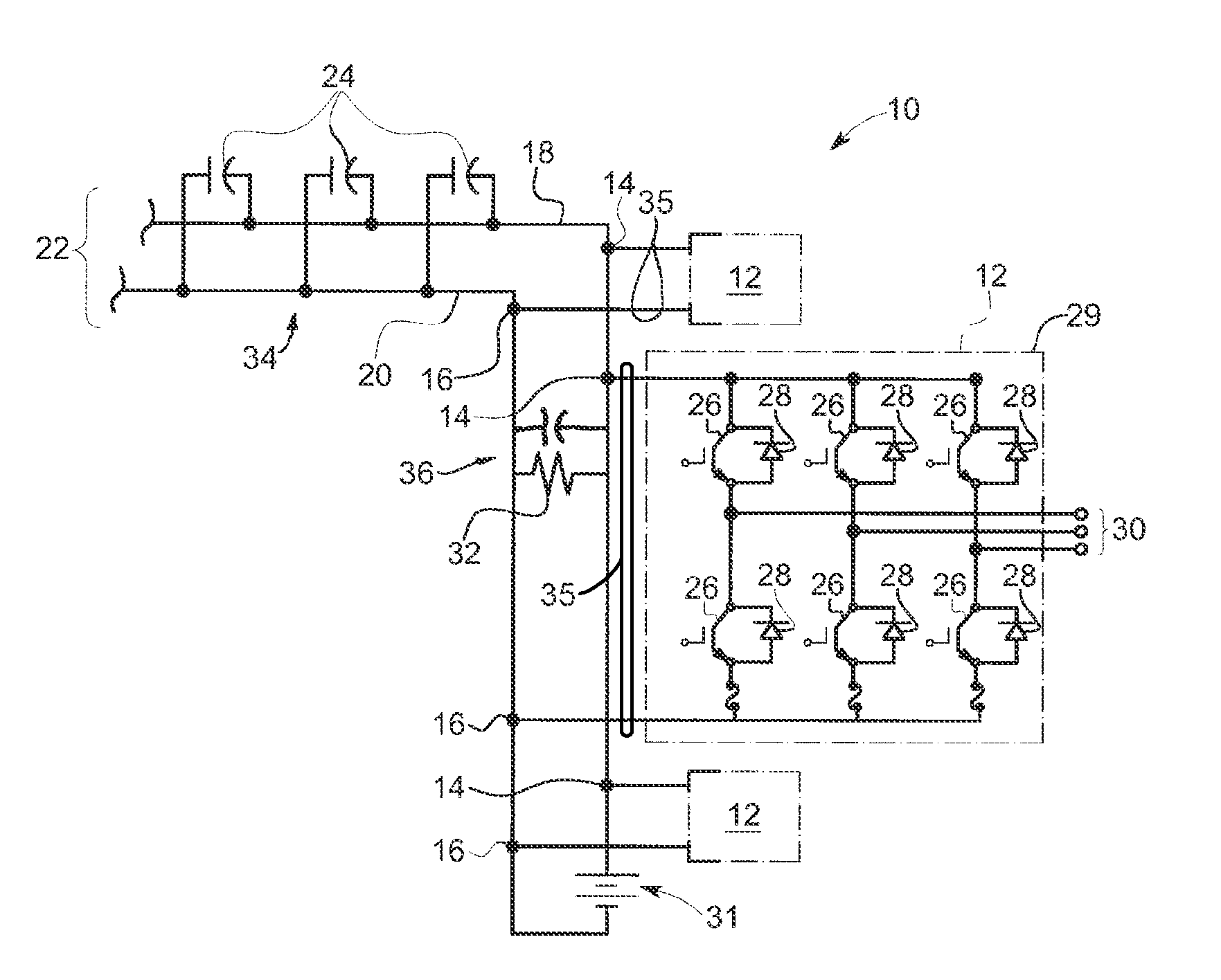
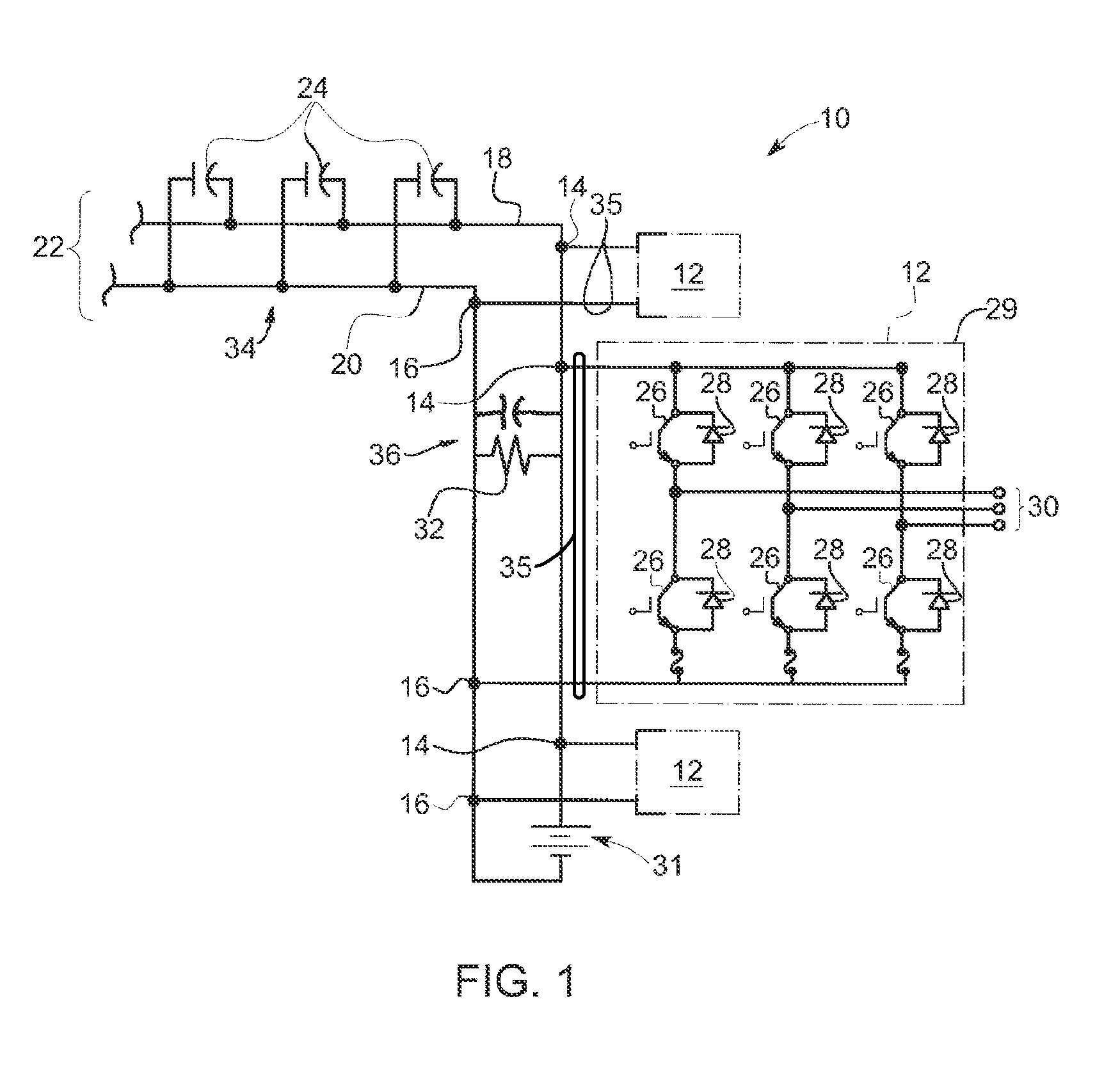
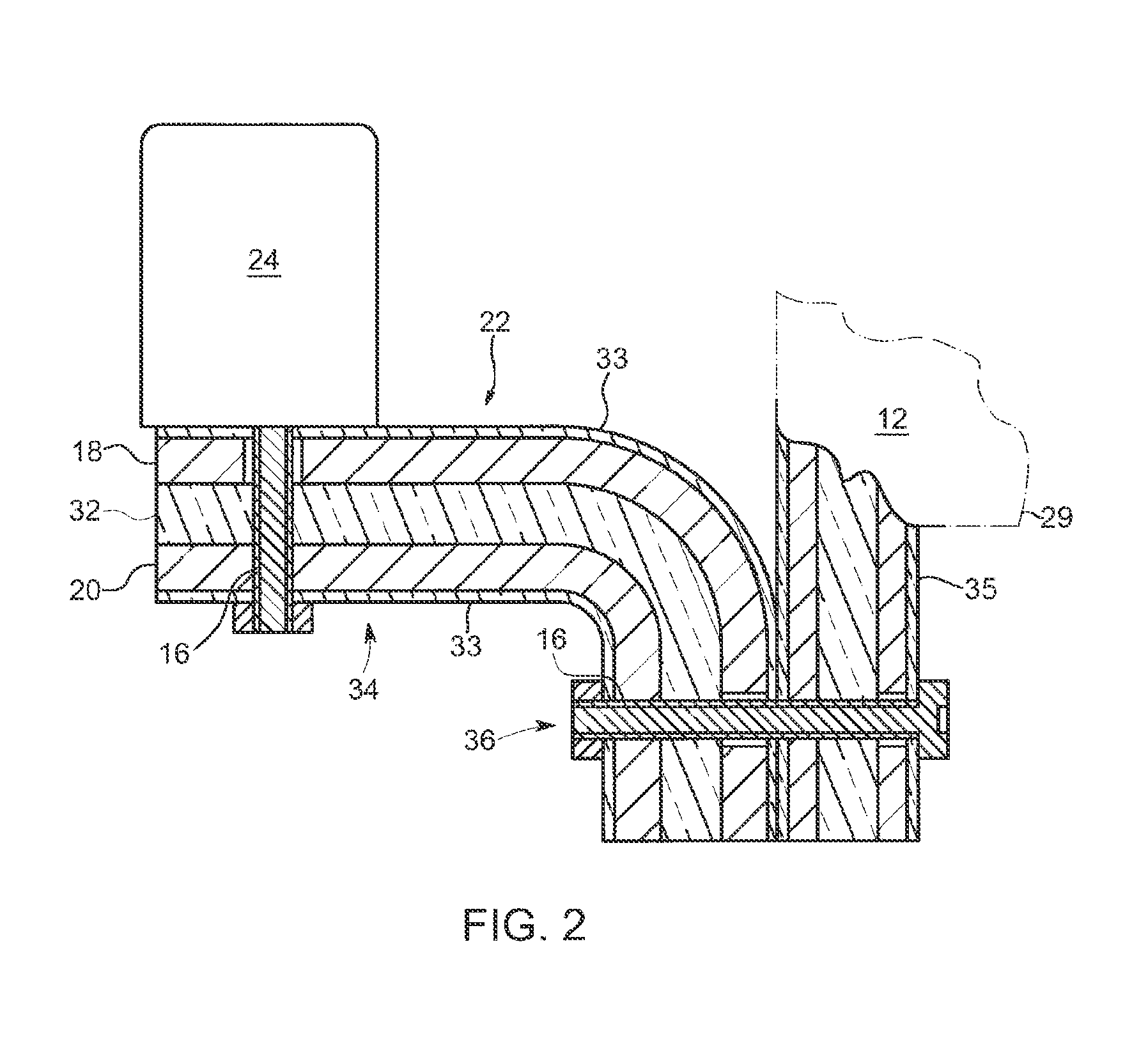
[0019]Aspects of the invention relate to modular power converters that are built without capacitors. Further aspects of the invention relate to power supplies built onto a laminated bus bar, such that the relatively low inductance of the bus bar permits effective parallel connection of numerous bus capacitors in a bank for absorbing voltage surges. Further aspects of the invention relate to such power supplies, in which the combined inductance of bus bars and bus capacitors is sufficiently small to ena...


PUM


Abstract

A capacitor bank includes a laminated bus bar having a high potential conductive layer and a low potential conductive layer disposed in close proximity at opposing surfaces of an intervening insulation layer. The bank also includes a plurality of bus capacitors electrically connected to the laminated bus bar. The laminated bus bar and the bus capacitors having a combined inductance sufficiently low such that the bus capacitors are electrically connected effectively in parallel with the laminated bus bar.

Description

BACKGROUND[0001]1. Technical Field[0002]Embodiments of the invention relate generally to power supplies. Particular embodiments relate to solid state switched power supplies.[0003]2. Discussion of Art[0004]Power supplies are electronic / electrical circuits that supply electric power to one or more electric loads. The term “power supply” is most commonly applied to collections or an assembly of electrical devices that convert one form of electrical energy to another and are commonly referred to as “power converters.” Many power supplies include two or more power converters connected together. Typically, power converters are “switching” power converters, in which multiple solid state devices are to used to intermittently interrupt an input current so as to effectuate conversion of the input current to an output current having different amplitude, voltage, and / or frequency. For example, an “AC power converter” receives direct or alternating input current and produces alternating output ...

Claims


Application Information

Patent Timeline
Patent Type & Authority Applications(United States)
IPC IPC(8): H01G2/00H02J1/00
CPCH02J1/00H01G2/00H01G11/10H01G2/04H01G2/08H05K7/14324H05K7/14329H05K7/1432Y02E60/13
Inventor YOUNG, HENRY TODDCURBELO, ALVARO JORGE MARIKUTTENKULER, JASON DANIELCILLESSEN, SEAN
Owner GENERAL ELECTRIC CO
Why Eureka
Try Eureka