
Absolute three-dimensional shape measurement using coded fringe patterns without phase unwrapping or projector calibration

a fringe pattern and three-dimensional measurement technology, applied in the field of three-dimensional shape measurement, can solve the problems of fundamental limitation of the method, the inability of the method to accurately and densely reconstruct many real-world objects, and the passive stereo method

Inactive Publication Date: 2014-03-20
IOWA STATE UNIV RES FOUND
View PDF9 Cites 52 Cited by
  • Summary
  • Abstract
  • Description
  • Claims
  • Application Information

AI Technical Summary

Benefits of technology

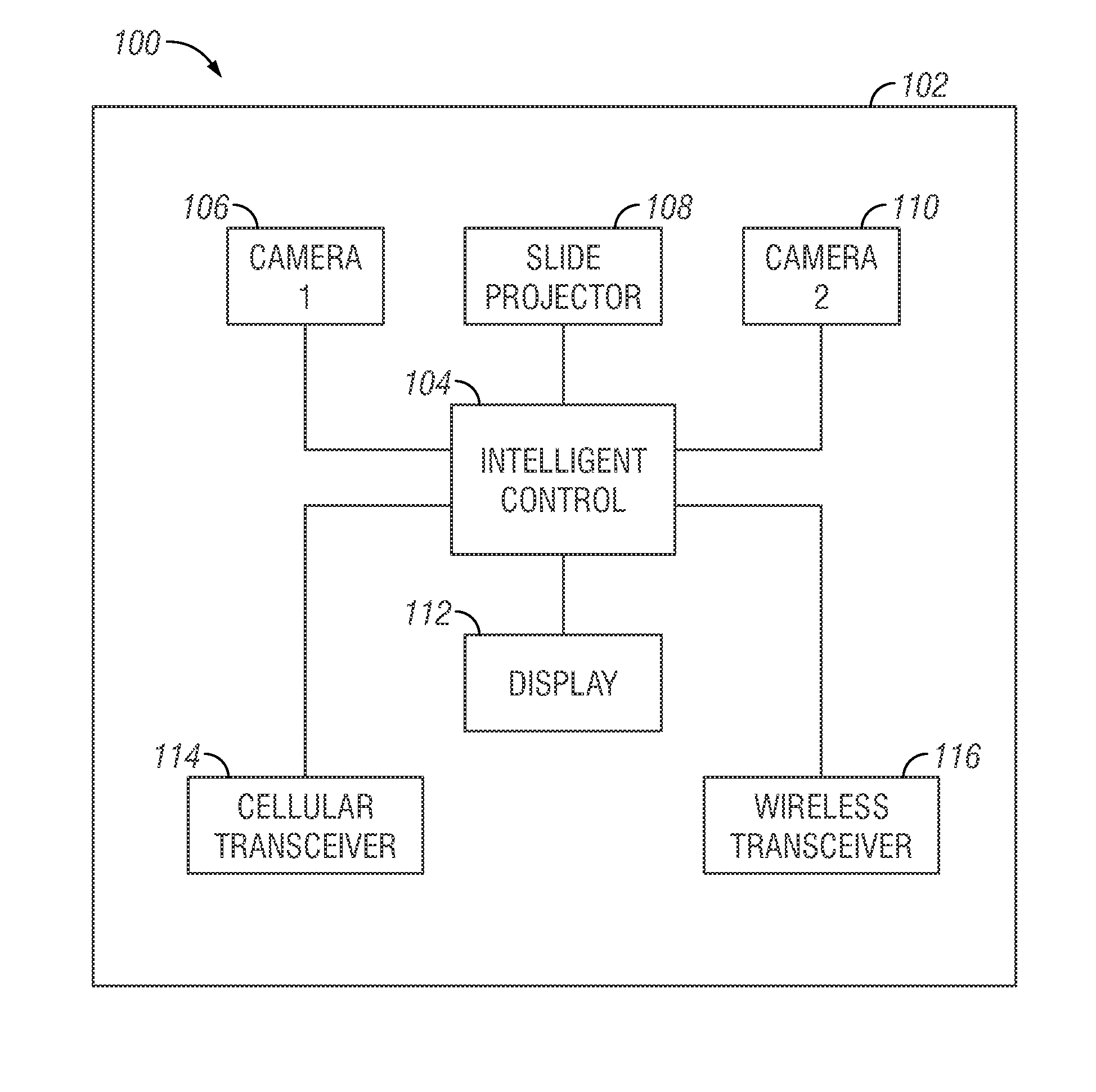
The present invention provides a method for three-dimensional shape measurement that overcomes several technical problems of the prior art. Firstly, it does not require any geometric constraint imposed by the projector. Secondly, it does not require projector calibration. Thirdly, it does not use a traditional spatial or temporal phase unwrapping algorithm. Fourthly, it does not require a high-quality phase map. Lastly, it is suitable for use with cell phones or other consumer devices.

Problems solved by technology

Detecting corresponding points between two stereo images is a well-studied problem in stereo vision.
Passive stereo methods, despite recent advances, still suffer from the fundamental limitation of the method: finding corresponding pairs between two natural images.
This requirement hinders the ability of this method to accurately and densely reconstruct many real-world objects such as uniform white surfaces.
While the active DFP technique has numerous advantages over passive stereo methods, it also suffers from several problems.
The spatial phase unwrapping cannot be used for large step-height or isolated object measurement, and the temporal phase unwrapping requires more images to be captured, slowing down the measurement speed.
Even though numerous projector calibration methods have been developed, accurate projector calibration remains difficult because, unlike a camera, a projector cannot directly capture images.
However, similar to prior phase-based methods, these methods require projector calibration, which is usually not easy and even more difficult for nonlinear projection sources.
Furthermore, the geometric constraint usually requires globally backward and forward checking for matching point location, limiting its speed and capability of measuring sharp changing surface geometries.

Method used


Image

  • Absolute three-dimensional shape measurement using coded fringe patterns without phase unwrapping or projector calibration
  • Absolute three-dimensional shape measurement using coded fringe patterns without phase unwrapping or projector calibration
  • Absolute three-dimensional shape measurement using coded fringe patterns without phase unwrapping or projector calibration

Examples


Embodiment Construction

1. Introduction

[0033]Triangulation-based three-dimensional (3D) shape measurement can be classified into two categories: the passive method (e.g. stereo vision) and the active method (e.g., structured light). In a passive stereo system, two images captured from different perspectives are used to detect corresponding points in a scene to obtain 3D geometry [1, 2]. Detecting corresponding points between two stereo images is a well-studied problem in stereo vision. Since a corresponding point pair must lie on an epipolar line, the captured images are often rectified so that the epipolar lines run across the row [3]. This allows a method of finding corresponding points using a “sliding window” approach, which defines the similarity of a match using cost, correlation, or probability. The difference between the horizontal position of the point in the left image and that in the right image is called the disparity. This disparity can be directly converted into 3D geometry.

[0034]Standard cos...


PUM


Abstract

A stereo-phase-based absolute three-dimensional (3D) shape measurement method is provided that requires neither phase unwrapping nor projector calibration. This proposed method can be divided into two steps: (1) obtain a coarse disparity map from the quality map; and (2) refine the disparity map using local phase information. Experiments demonstrated that the proposed method could achieve high-quality 3D measurement even with extremely low-quality fringe patterns. The method is particular well-suited for a number of different applications including in mobile devices such as phones.

Description

FIELD OF THE INVENTION[0001]The present relates to three-dimensional shape measurement.BACKGROUND OF THE INVENTION[0002]Triangulation-based three-dimensional (3D) shape measurement can be classified into two categories: the passive method (e.g. stereo vision) and the active method (e.g., structured light). In a passive stereo system, two images captured from different perspectives are used to detect corresponding points in a scene to obtain 3D geometry [1, 2]. Detecting corresponding points between two stereo images is a well-studied problem in stereo vision. Since a corresponding point pair must lie on an epipolar line, the captured images are often rectified so that the epipolar lines run across the row [3]. This allows a method of finding corresponding points using a “sliding window” approach, which defines the similarity of a match using cost, correlation, or probability. The difference between the horizontal position of the point in the left image and that in the right image is...

Claims


Application Information

Patent Timeline
Patent Type & Authority Applications(United States)
IPC IPC(8): G01B11/25H04N9/31H04N13/02H04N13/239
CPCG01B11/2545H04N9/31H04N13/0239G01B11/2513G06T2207/10012G06T7/521G06T7/593H04N13/254H04N13/239G01B11/2527
Inventor ZHANG, SONG
Owner IOWA STATE UNIV RES FOUND
Learn More